

 |
Jack Ganssle's Blog This is Jack's outlet for thoughts about designing and programming embedded systems. It's a complement to my bi-weekly newsletter The Embedded Muse.
Contact me at jack@ganssle.com. I'm an old-timer engineer who still finds the field endlessly fascinating (bio).
This is Jack's outlet for thoughts about designing and programming embedded systems. It's a complement to my bi-weekly newsletter The Embedded Muse.
Contact me at jack@ganssle.com. I'm an old-timer engineer who still finds the field endlessly fascinating (bio). |
Fun With Transmission Lines
August 16, 2018
In the digital world we thrive in a pristine world of zeros and ones. Logic elements cleanly switch. Analog messiness doesn't exist.
Except that's not entirely true. Digital is merely an idealized version of the real analog universe.
And then there's transmission lines and RF issues. Drive a clean digital signal down a track on a PCB and all sorts of weirdness can happen.
One of the best books on electronics, The Art of Electronics, by Horowitz and Hill, has a cool example of this. Want to generate a pulse from a step waveform? Well, we'd normally design a bit of logic to do so, but their thought experiment is pretty eye-opening.
Suppose you've got a bit of coax. If it's terminated by a short circuit, a step fed into it will generate a reflection that is the inverse of the applied step. That reflection is delayed by a length of time equal to the round-trip length of the coax. It will null out all but an initial pulse of the step.
RG-58U has a characteristic impedance (Z0) of 50 ohms, so we design the circuit thusly:
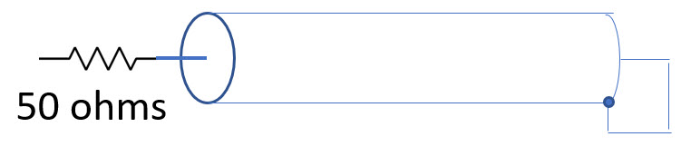
I configured my arbitrary waveform generator to create a pulse with a reasonable sharp leading edge (8 ns - the best it can do) and monitored both the AWG's output (on channel 1) and the input to the coax (the right side of the resistor). The result:
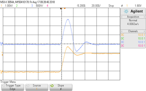
You can see the reflected signal turns the step waveform from the AWG to a pulse.
At first I wondered why the voltage goes to, and stays at, zero volts after the pulse. D'oh - the far side of the coax is grounded.
Horowitz and Hill claim the ratio of the two signals is (R-Z0)/(R+Z0), where R is the terminating resistor at the coax's far end - 0 ohms in this example. The experimental results are reasonably close to this. I suspect the non-perfect rise time affects the result.
RF electronics is quite interesting and a lot of fun. One of the best references on the subject, if you don't want to go into the dreaded details of Maxwell's Laws, is The ARRL Handbook for Radio Communications. The ARRL is the advocacy group for radio hams. I've had a license since 1969 (callsign N3ALO), but have always enjoyed building and understanding radios more than using them.
Feel free to email me with comments.
Back to Jack's blog index page.
If you'd like to post a comment without logging in, click in the "Name" box under "Or sign up with Disqus" and click on "I'd rather post as a guest."
Recent blog postings:
- Non Compos Mentis - Thoughts on dementia.
- Solution to the Automotive Chip Shortage - why use an MCU when a Core I7 would work?
- The WIRECARE - A nice circuit tester
- Marvelous Magnetic Machines - A cool book about making motors
- Over-Reliance on GPS - It's a great system but is a single point of failure
- Spies in Our Email - Email abuse from our trusted friends
- A Canticle for Leibowitz - One of my favorite books.
- A 72123 beats per minute heart rate - Is it possible?
- Networking Did Not Start With The IoT! - Despite what the marketing folks claim
- In-Circuit Emulators - Does anyone remember ICEs?
- My GP-8E Computer - About my first (working!) computer
- Humility - On The Death of Expertise and what this means for engineering
- On Checklists - Relying on memory is a fool's errand. Effective people use checklists.
- Why Does Software Cost So Much? - An exploration of this nagging question.
- Is the Future All Linux and Raspberry Pi? - Will we stop slinging bits and diddling registers?
- Will Coronavirus Spell the End of Open Offices - How can we continue to work in these sorts of conditions?
- Problems in Ramping Up Ventilator Production - It's not as easy as some think.
- Lessons from a Failure - what we can learn when a car wash goes wrong.
- Life in the Time of Coronavirus - how are you faring?
- Superintelligence - A review of Nick Bostrom's book on AI.
- A Lack of Forethought - Y2K redux
- How Projects Get Out of Control - Think requirements churn is only for software?
- 2019's Most Important Lesson. The 737 Max disasters should teach us one lesson.
- On Retiring - It's not quite that time, but slowing down makes sense. For me.
- On Discipline - The one thing I think many teams need...
- Data Seems to Have No Value - At least, that's the way people treat it.
- Apollo 11 and Navigation - In 1969 the astronauts used a sextant. Some of us still do.
- Definitions Part 2 - More fun definitions of embedded systems terms.
- Definitions - A list of (funny) definitions of embedded systems terms.
- On Meta-Politics - Where has thoughtful discourse gone?
- Millennials and Tools - It seems that many millennials are unable to fix anything.
- Crappy Tech Journalism - The trade press is suffering from so much cost-cutting that it does a poor job of educating engineers.
- Tech and Us - I worry that our technology is more than our human nature can manage.
- On Cataracts - Cataract surgery isn't as awful as it sounds.
- Can AI Replace Firmware - A thought: instead of writing code, is the future training AIs?
- Customer non-Support - How to tick off your customers in one easy lesson.
- Learn to Code in 3 Weeks! - Firmware is not simply about coding.
- We Shoot For The Moon - a new and interesting book about the Apollo moon program.
- On Expert Witness Work - Expert work is fascinating but can be quite the hassle.
- Married To The Team - Working in a team is a lot like marriage.
- Will We Ever Get Quantum Computers - Despite the hype, some feel quantum computing may never be practical.
- Apollo 11, The Movie - A review of a great new movie.
- Goto Considered Necessary - Edsger Dijkstra recants on his seminal paper
- GPS Will Fail - In April GPS will have its own Y2K problem. Unbelievable.
- LIDAR in Cars - Really? - Maybe there are better ideas.
- Why Did You Become an Engineer? - This is the best career ever.
- Software Process Improvement for Firmware - What goes on in an SPI audit?
- 50 Years of Ham Radio - 2019 marks 50 years of ham radio for me.
- Medical Device Lawsuits - They're on the rise, and firmware is part of the problem.
- A retrospective on 2018 - My marketing data for 2018, including web traffic and TEM information.
- Remembering Circuit Theory - Electronics is fun, and reviewing a textbook is pretty interesting.
- R vs D - Too many of us conflate research and development
- Engineer or Scientist? - Which are you? John Q. Public has a hard time telling the difference.
- A New, Low-Tech, Use for Computers - I never would have imagined this use for computers.
- NASA's Lost Software Engineering Lessons - Lessons learned, lessons lost.
- The Cost of Firmware - A Scary Story! - A hallowean story to terrify.
- A Review of First Man, the Movie - The book was great. The movie? Nope.
- A Review of The Overstory - One of the most remarkable novels I've read in a long time.
- What I Learned About Successful Consulting - Lessons learned about successful consulting.
- Low Power Mischief - Ultra-low power systems are trickier to design than most realize.
- Thoughts on Firmware Seminars - Better Firmware Faster resonates with a lot of people.
- On Evil - The Internet has brought the worst out in many.
- My Toothbrush has Modes - What! A lousy toothbrush has a UI?
- Review of SUNBURST and LUMINARY: An Apollo Memoir - A good book about the LM's code.
- Fun With Transmission Lines - Generating a step with no electronics.
- On N-Version Programming - Can we improve reliability through redundancy? Maybe not.
- On USB v. Bench Scopes - USB scopes are nice, but I'll stick with bench models.