|
||||
You may redistribute this newsletter for non-commercial purposes. For commercial use contact jack@ganssle.com. To subscribe or unsubscribe go here or drop Jack an email. |
||||
| Contents | ||||
| Editor's Notes | ||||
Over 400 companies and more than 7000 engineers have benefited from my Better Firmware Faster seminar held on-site, at their companies. Want to crank up your productivity and decrease shipped bugs? Spend a day with me learning how to debug your development processes. Attendees have blogged about the seminar, for example, here, here and here. Any idea how much code is in a modern car? Take a guess (in lines of code) and then scroll down to the Tools and Tips section of this newsletter for the answer. Jack's latest blog: Millennials and Tools - A recent report claims tons of young folks don't own a screwdriver. Yikes! |
||||
| Quotes and Thoughts | ||||
The future is uncertain - you can count on it. Anonymous |
||||
| Tools and Tips | ||||
Please submit clever ideas or thoughts about tools, techniques and resources you love or hate. Here are the tool reviews submitted in the past. How much code is there in a modern vehicle? According to the June issue of IEEE's Computing Edge magazine, in 2016 Ford announced their F-150 pickup has 150 million lines. |
||||
| Freebies and Discounts | ||||
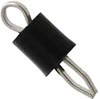
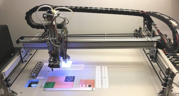
The folks at LitePlacer are offering a pick and place machine, in kit form, to Muse readers this month. This looks like a very cool robot:
Enter via this link. |
||||
| Multicore Scaling | ||||
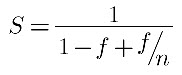
We live in a golden age of computing. Need 10,000 servers to solve a problem? Amazon Web Services makes that easy and inexpensive. Short on CPU cycles in your embedded system? Multicore to the rescue. Amdahl's Law purports to tell us how much speedup we can expect as a function of the number of processors used (n) and the fraction of a problem that is parallelizable (f):
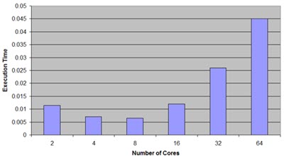
If f is 1 (everything can run in parallel) than the speedup is just the number of processors. Conversely, if the entire problem must run sequentially adding cores does nothing for you other than cost money and power. (Gustafson's law shows that Amdahl's version is pessimistic for some classes of problems). But Amdahl doesn't account for shared memory, a key characteristic of multicore systems. Typically each core hides behind its own small cache, but main memory is all on a single shared bus. If more than one core needs access to memory, all but one stalls. Sandia National Labs has shown this to be a problem even on programs with tremendous amounts of parallelism. For instance:
A new paper (Estimation of Maximum Speed-Up in Multicore-Based Mobile Devices, Yonghee Yun, Sodam Han, and Young Hwan Kim, IEEE Embedded Systems Letters, Vol. 11 No. 2, June 2019 - full disclosure: I'm on the publication's advisory board) estimates speedups attained in Arm big.LITTLE processors. These MCUs mix typically one or more fast cores with some smaller CPUs. For instance, NXP's SAC57D54H dishes up a big Cortex A5 with LITTLE M4 and M0+ cores. The paper posits that speedups in big.LITTLE systems can be computed by:
nbig is the number of big cores, fk the parallelizable fraction of the code on each of those, I think there's a mistake in the formula: if fk and fi are both zero, meaning there's no parallelizable part of the code, it gives a speedup of infinity. Probably missing is a leading "1-" in the denominator. There are some issues with the formula. The SAC57D54H I referenced has two different LITTLE cores so The authors show that for a variety of real-world problems the formula does match their experimental results remarkably well, so is a useful addition to our quiver of analysis tools. |
||||
| Review: Siglent's New SDS5034X Oscilloscope | ||||
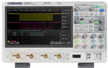
Siglent is a Chinese manufacturer of test equipment I've been following closely. They offer a wide range of instruments, and they, along with other Chinese vendors, have changed the oscilloscope business. Today you can get a high-quality scope for a fraction of what we paid a handful of years ago. They've recently released a new series of scopes. Big screen. Big. 10.1". And did I mention it's big? That's the first thing you notice when unpacking Siglent's new SDS5000X oscilloscopes which are their flagship products.
First, the basics:
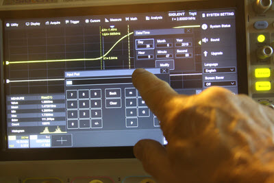
They sent me the SDS5034X, a 350 MHz four-channel model with the digital channels. Do you like touchscreens? I'm mixed. Marybeth's computer has one, and every time she has a computer question my first response is to point to, and touch, an item on the screen. This always screws things up. My AWG has a little touchscreen that I mostly find annoying. The SDS5034X also has one, but the screen is so huge that the touch feature works brilliantly. Should you dislike this feature a "Touch" button disables it. There is one quirk: with the touch feature disabled, the only way to select various parameters in menus is with a mouse, so we mouseless scope operators will need to leave touch enabled. Operating the scope feels a bit like using an iPad. For example, when entering the time one can move the window just by sliding your finger around the screen.
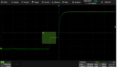
Want to move a cursor? Sure, the knobs will do so, but it's easier to just touch the desired cursor and move it with your finger. It's easy and feels natural. The two-fingered pinch and zoom will adjust the vertical gain or timebase, though I feel I have more control with the knobs when changing these settings. A menu across the top of the screen gives touch access to pretty much all of the instrument's functionality. The more I used the scope, the more I relied on the touchscreen. An interesting feature is the "+" field in the lower left hand corner of the above picture. Press it to quickly enable another channel, be it analog, digital, a math function or a reference waveform. I don't have the gear to measure the bandwidth of a scope rated at 350 MHz, but using my homemade SquarerUpper tool, the scope displayed a 700 ps risetime as 1.46 ns, quite good for a scope of this bandwidth.
A few nice features:
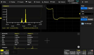
The unit does all of the usual measurements, and has a very nice histogram feature. In the following picture it's measuring the rise time and width of a pulse. On the bottom are two small histograms, one for each measurement. Dragging one with a finger up to the main part of the screen enlarges it. This feature changes the entire nature of an oscilloscope, which traditionally gave only snapshots of waveforms. Sure, digital scopes generally also give min, max, and standard deviation. But a histogram shows the distribution of values. That's pretty cool.
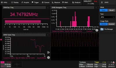
A lot of measurements are supported. I would probably never use many as I'd not remember that they existed. In most cases I'd eyeball the waveforms, perhaps using cursors. These more esoteric measurements are probably of use only when looking at their statistics. Math operations are the usual (+, -, *, /, FFT, d/dt, ∫dt, √). You can create two of these and combine them to form g[f(x)]. There's a DVM that will measure various kinds of voltages, frequency and period. While sort of nice, this is a very common feature. But there's a twist: the scope can create a bar graph, a histogram and a trend line from that data:
This is an excellent feature that makes the scope a recording meter. Oh, and these graphs are windows that you can move around with your finger. A 350 MHz 2-channel version of this scope goes for $2900, at 1 GHz with 4 channels it's $7300. The 16 digital channel option adds $800. The scope I tested goes for $4700. It's available here in the States from Saelig. I like this scope. A lot. I tried hard to find things I didn't like but came up blank. Well, it's not as pretty as those from Keysight and Tektronix; the knobs are a bit cheap-looking. And the option arbitrary waveform generator (which I did not test) is not inside of the scope; it's an add-on instrument the scope drives over a USB port. |
||||
| More on Test Points | ||||
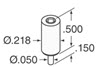
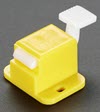
In the last Muse readers had ideas about adding test points to a PCB. More ideas flowed in. Phil Pemberton wrote:
Ray Keefe suggested:
|
||||
| Asserts Redux | ||||
Tom McCormick responded to my thoughts about the assert() macro:
Tom's comment raises some interesting issues. He's right, as the presence of the NDEBUG switch disables the assert() macro, so debug and release builds have different functionality. NASA's philosophy is test what you fly, fly what you test. In other words, don't do your testing, and then change the code! Yet there may be very good reasons for having assert() behave differently between build types. What should assert() or any other bug-catching code do in a release build? In some systems there may be graceful recovery schemes, though it's hard to imagine one that applies to every possible bug assert() would detect. Tom's approach lets one tailor the system's response to a particular detected failure: the error handling code can vary from bug to bug. Or, one could write assert() to enter a safe mode (e.g., on a spacecraft the system goes to minimal functionality, orients the solar cells to the sun, and handles ground commands). In that case, assert() could be the same in both debug and release builds; in the former you set a breakpoint on entry to the safe mode code. Back in the 70s we built a system with an error mode that could never happen, and, as a joke, we coded a message that said "Error: Call (301)-XXX-XXXX and give Harold hell." Except it did occur. Harold was not happy. |
||||
| Jobs! | ||||
Let me know if you’re hiring embedded engineers. No recruiters please, and I reserve the right to edit ads to fit the format and intent of this newsletter. Please keep it to 100 words. There is no charge for a job ad.
|
||||
| Joke For The Week | ||||
Note: These jokes are archived here. You might be an engineer if:
|
||||
| About The Embedded Muse | ||||
The Embedded Muse is Jack Ganssle's newsletter. Send complaints, comments, and contributions to me at jack@ganssle.com. The Embedded Muse is supported by The Ganssle Group, whose mission is to help embedded folks get better products to market faster. |


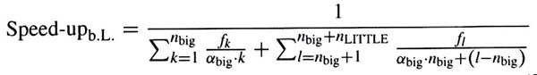
 is a constant that denotes the speed difference between the big and LITTLE cores, nLITTLE is the number of LITTLE cores, and fl is the parallelizable fraction of the code on those LITTLE guys.