Go here to sign up for The Embedded Muse.
The Embedded Muse Logo The Embedded Muse
Issue Number 367, February 4, 2019
Copyright 2019 The Ganssle Group

Editor: Jack Ganssle, jack@ganssle.com

   Jack Ganssle, Editor of The Embedded Muse

You may redistribute this newsletter for non-commercial purposes. For commercial use contact jack@ganssle.com. To subscribe or unsubscribe go here or drop Jack an email.

Contents
Editor's Notes

Express Logic

Over 400 companies and more than 7000 engineers have benefited from my Better Firmware Faster seminar held on-site, at their companies. Want to crank up your productivity and decrease shipped bugs? Spend a day with me learning how to debug your development processes.

Attendees have blogged about the seminar: here, here and here.

Jack's latest blog: Why Did You Become an Engineer?

Quotes and Thoughts

"What makes an expert isn't so much what they know, It's that they've done similar things so many times wrong They know what not to do." - Wayne Mitzen

Tools and Tips

SEGGER emCompress Real Time Compression

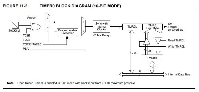
Please submit clever ideas or thoughts about tools, techniques and resources you love or hate. Here are the tool reviews submitted in the past.

Mohd Lee responded to comments in Muses 355, 356 and 357 about asynchronous sampling, where the discussion focused on the problem of multiple reads of an input whose value is changing. A common problem is reading a 16-bit timer with an 8-bit MCU. Mohd wrote:

In some series of 8-bit Microchip PICs, there is a 16-bit mode for the timer which has a clever buffer for the high byte. The high byte updates when the low byte is being read, and when writing it will update the 16-bit register in one operation, saving quite a bit of code and headache, and also introduce newbies to this concept.

MIcrochip PIC timers without an async read problem

Thor wrote:

For those who just haven't mustered up the cash for a "real" logic analyzer, my favorite tool is the Bus Pirate (https://amzn.to/2Ta6L2u). It can do quite a few things and it speaks SUMP so you can use a nice frontend for it if you want.

I must confess though... my main use for it is to sent I2C messages to chips to figure out why my main MCU isn't liking the IO chips... the Bus Pirate  makes it easy and has an onboard 3v3 power supply so you can tack a few wires on and roll with it.  You can also clip to your leads and it makes a dandy I2C logger for your output code.

Fits in a "large" tic-tac box for safekeeping ;)

The Mini-USB cables, OTOH, are getting rare...

Freebies and Discounts

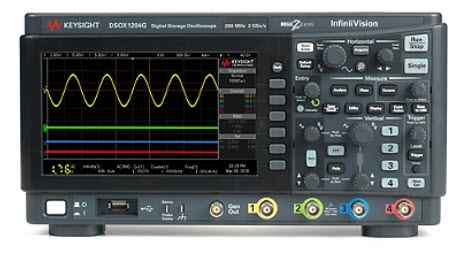
Courtesy of the fine folks at Keysight, this month's giveaway is one of their brand new DSOX-1204G bench 200 MHz 4-channel scopes:

Keysight DSOX1204G oscilloscope

Enter via this link. Also, at the end of the scope's review (next article) there are links for a contest Keysight is running, where they will be giving away a number of these and lots of other test equipment.

Review: Keysight's New DSOX1204G Scope

Keysight has a couple of new additions to their DSOX1000 series of low-cost oscilloscopes. The new models bring four channels to bear with up to a 200 MHz bandwidth. That doubles both specs compared to their earlier units in this line. The company kindly sent two of their DSOX1204G units for evaluation and as contest offerings. One is the contest offering this month and the other next month. See the picture above.

First, the specs:

  • Bandwidth: 70, 100 or 200 MHz available (they sent the 200 MHz version)
  • Channels: 4
  • Sample rate: 2 GSa/s
  • Memory: 1 Mpts
  • Update rate: 50,000 waves/s
  • Screen: 7", 800 x 480 pixels
  • Vertical resolution: 8 bits
  • Vertical gain: 500 uV (with X1 probe) to 10 V/div
  • Time base range: 5 ns to 50 s/div according to the datasheet, but the scope I tested could go down to 2 ns/div
  • Waveform generator: standard in the "G" model, not available otherwise
    • Sine, square, ramp, pulse, DC, noise, with AM, DM and FSK modulation
    • Sine wave to 20 MHz, square/pulse to 10 MHz, ramp to 200 kHz
  • Protocol decoders: optional

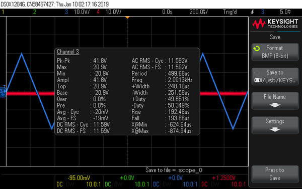
The base price for the 4-channel version at 70 MHz is $998, or $1204 with the waveform generator. The 200 MHz version I tested had all the options and goes for $2214.

First, the screen: It's crisp, easy to read, and there's no waveform jitter like you see on some of the Chinese units (the unit does sport a "made in China" sticker). The writing is small (as is the case on pretty much all scopes today) but very clear. I do have to squint to read the time base units: is it µs or ns? Some of that is probably attributable to soon-to-be-fixed cataracts.

If you've used one of Keysight's InfiniiVision scopes the user interface will be very familiar.

There are two ways to implement a four-channel scope: have four separate sets of vertical controls or use one set, with buttons to select which channel the controls effect. Keysight chose the latter. A LED changes color to indicate the selected channel, and that color scheme is unified throughout the scope, including the color of the trace on the screen.

The unit is small and very portable at 314 mm x 165 mm x 130 mm and 3.2 kg.

Today it's hard to differentiate scopes as so many have similar features. Pretty much all do a decent job of sucking in and displaying signals, so I'll point out the DSOX1204G's differentiating features.

First, a "Quick Action" button can be configured to save to a USB stick, clear the display, and a few other things. For me, the only value I see is to set this to "Measure All", which pops up an ocean of measurements:

DSOX1204G measurements

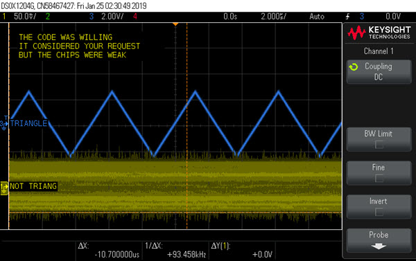
The "Display" button sets the usual things like persistence and the grid. But it also allows one to attach labels to waveforms and put annotations on the screen. I like this a lot as it makes documenting a screen shot much easier. Remember scope cameras, huge, bulky Polaroid beasts that were positioned over the screen? We'd use a sharp pointer to scratch labels on the resulting picture.

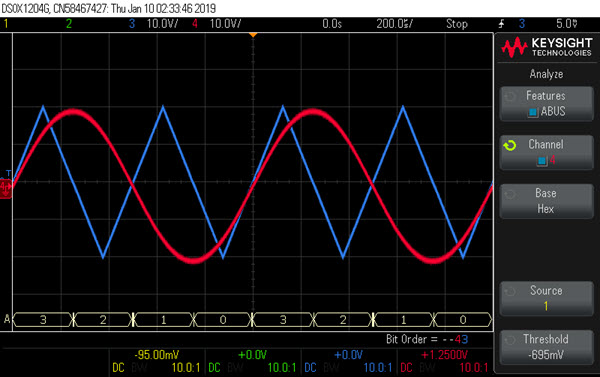
The user manual leaves a lot to be desired. For instance, it's pretty much silent on what a "pattern" trigger is. All of the controls do have excellent context-sensitive help, and pressing the "Trigger Type Pattern" soft switch was illuminating. A pattern trigger is the logical AND of a set of the input channels. Legal values are 1, 0, X, and a rising or falling edge.

This is not a mixed signal scope: there are no digital inputs. However, an interesting and surprising feature is the ability to group two or more of the channels into an "analog bus." The scope decodes the channels into ones and zeroes. In the following example, channel 4 is the MSB and 3 is the LSB; the white bus at the bottom shows the digital values. Here I'm using analog waveforms, which is silly but fun. More likely you'd be scoping logic levels:

DSOX1204G analog bus

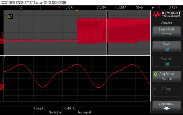
Very cool, and a sweet way to get logic analyzer-like capability.

Like pretty much all digital scopes, the DSOX1204G has a zoom mode that is often under-appreciated:

DSOX1204G fast acquisition

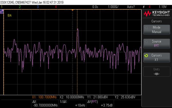
The top trace was acquired at 1 µs/div. Something weird is going on but it's hard to see what. The bottom trace is zoomed to 2 ns/div and shows more detail.

The sample rate is 2 GSa/s - nominally. With a slow time base that will decrease, of course. With more than one channel enabled that falls to 1 GSa/s. With all four on, the rate doesn't drop further.

While the sample rate is displayed on the right-side of the screen, it's often covered up by other menus. Pressing the "Back" button one or two times will reveal it, but this parameter is so important I wish it were never hidden.

The scope supports segmented memory, a very powerful and useful feature. I described this in some detail in Muse 315 so will gloss over it here, but this feature allows one to split the memory buffer into up to 50 chunks; each trigger event fills one chunk. That's useful if you want to capture multiple instances of something that happens slowly compared to the horizontal rate. I don't use that feature often, but sometimes it's a lifesaver, although, in practice, it's pretty unusual for a scope to save a life.

Like all digital scopes the DSOX-1204G has a number of math operations: add, subtract, multiply, divide, FFT and, nicely, a low-pass filter. The filter's bandwidth is variable from 1 Hz to 200 MHz. While each channel does have the usual bandwidth limiter, this feature lets you fine-tune the displayed signal. I haven't seen this in inexpensive scopes before. Suggestion to Keysight: add a mode where the signal, after going through the low-pass filter, comes out the waveform generator's BNC - that would be a nifty tool for the lab.

It also has the mask testing feature that I described in Muse 358.

A waveform generator is standard in the 1204G model. Rise time for square waves and pulses is spec'd at 18 ns which is what I measured. That's fairly typical for low-cost generators but does mean that a 10 MHz square wave is rather siney-looking.

Usually a scope's FFT (Fast Fourier Transform) selection is buried in a menu. On the DSOX1204G it gets its own button. One fun thing to do with an FFT is to survey the radio spectrum. I ran a meter of wire as an antenna into one of the scope's channels. The following picture shows the FFT with a center frequency of 100 MHz with a 20 MHz span, mostly covering the commercial FM band. Sure enough, the cursor is on a peak at 100.70 MHz, the carrier frequency of the strongest Baltimore station we get out here in beautiful downtown Finksburg:

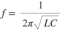
One feature that really stands out is the scope's "frequency response analysis" (FRA). Having an FFT is somewhat akin to getting a spectrum analyzer (SA) for free. With the FRA the unit is like a SA with a tracking generator. The waveform generator's sine wave is swept in frequency between two values while monitoring the input and output of an AC network. A Bode plot of amplitude and phase shift is then displayed.

A little electronics is in order: Feed AC through a capacitor or inductor and you'll find the waveform phase-shifted and attenuated. The amount of these distortions is highly frequency dependent. Wire an inductor and capacitor in series or parallel and at some frequency the network becomes resonant. If in parallel the LC's combined reactance (AC resistance) goes to a high value. That frequency is given by:

Equation for resonance in an LC circuit

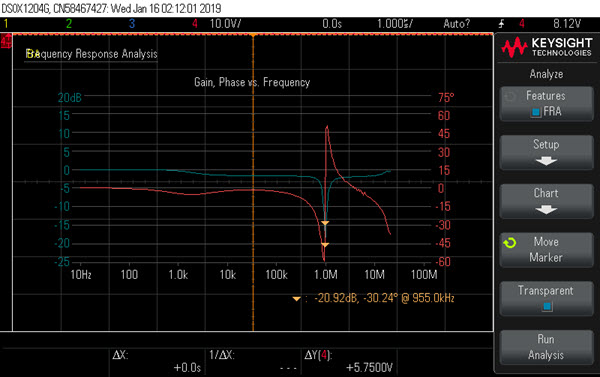
I wired a 75 uH inductor in parallel with a 470 pF capacitor and had the scope create a Bode plot of the network:

DSOX1204G Bode plot

The blue trace is the amplitude of the signal through the network; the red is the phase shift. Orange numbers under the graph show that, at the marker, the signal is 21 dB down from nominal, with a 30-degree phase shift, and the resonance frequency is 955 KHz. Moving the marker just one pixel to the right changed the frequency to 1 MHz; my spectrum analyzer showed a minimum at 978 KHz. Now, these numbers are off from the computed 847.7 KHz resonance frequency, but the inductor is rated ± 10% and the cap ±20%.

In English: the series LC circuit blocks the signal at all frequencies except near resonance. A parallel LC would show an opposite effect.

The tracking generator on a SA sweeps continuously, smoothly. I watched the Keysight's waveform with another scope and found it changes frequency in discrete quanta. A control selects how many of these points should be used. Start and end frequencies are also selectable in decade ranges. In the image above there are 50 points per decade (the max allowed), with frequencies from 10 Hz to 20 MHz (the min and max, respectively).

Why must one of the channels must monitor the waveform into the network? After all, the scope knows what frequency it's generating. The reason is one could probe various stages of a multiple pole filter and the input to a stage of interest could be phase shifted from the scope's waveform generator.

The waveform generator's max is 20 MHz, which means no Bode plots for higher frequencies. That constraint is understandable... but it sure would be cool to be able to profile wider. Regardless, if you're working on LF or HF gear this is a killer feature.

It can connect to a network, of course, and it has its own web server which apparently lets you control everything; I didn't try this.

I consider a 100 MHz scope about the minimum for embedded work and two channels barely adequate. The DSOX-1204G with a 200 MHz bandwidth and four channels will fulfill most developers' needs. If you don't have a mixed-signal scope the analog bus is very useful in digital work, and if you're working with sub-20 MHz RF, the FRA is very valuable.

All in all, this is an extremely nice scope at an attractive price point.

More on Artificial Intelligence

Last issue's thoughts about AI generated gobs of comments from readers. I was surprised by how many are skeptical about the future of AI as it is currently envisioned. It's true that there has been a lot of hype and a lot of hope about making machines "intelligent" for a very long time. In 1970 when looking at colleges my dad took me to his alma mater, MIT, where we visited Marvin Minsky's AI lab. Minsky was working on "strong AI," which mostly bombed, but I still have a bit of lust in my heart for his PDP-12. (I didn't apply to MIT: everyone I saw was studying, not a smile was to be found).

Today goals are more modest and successes more common. My son works in data science and uses AI very successfully to make sense of enormous data sets. Though the field dates to the 1950s, now there's - almost suddenly - much more capability being deployed, like huge clusters of GPUs in data centers. Contrast that to a single 12-bit PDP-12 in 1970.

I'm very enthusiastic for the coming capabilities, but temper that with concerns about AI drawing incorrect conclusions about something truly important, and the inevitable political/legislative issues that will arise. The European Union's new General Data Protection Regulations already seem to address how misuse of automated reasoning may lead to big fines. Big, meaning possibly billions of dollars.

One of the issues I see with AI as it is today is the difficulty of understanding why an AI device makes a decision. John Lagerquist sent a link to an article about work being done to gain visibility into how an AI network generates conclusions.

Jakob Engblom sent this article which examines where AI is/should be going. It's a bit wordy but thought-provoking. An interesting point the author makes is that today AI is mostly being used in areas where mistakes are not a big deal. That will surely change.

Luca Matteini wrote:

I liked a lot your pun on AI/"Ain't Intelligent", and I have a couple of thoughts on that subject.

The claim that there's no way to verify what an (/any?) AI system has learned is just partially true, in my humble opinion. Just as much as I can tell that a complex enough conventional control system can give unpredictable results with unforeseen inputs (as shown by many incidents that we witness, from time to time).

Take as an example a NN pattern classifier, if you feed it with a test input vector you'll see what the output yields. What about /any/ possible pattern? I just doubt that this testing is viable, whatever is the control system, if we take enough input variables.

There's more, let's talk about NN inversion, determining which output maps to a specific input.

Even if this is probabilistic, already in the early 90's I used SNNS (Stuttgart Neural Network Simulator) as a test simulator, with an inversion analysis feature: http://bit.ly/2B0b8Gm

Its result was really interesting, as I used it for image pattern classification, so the display was immediately meaningful.

Then there's a second thought, more about hype. Talking about "AI" is /cool/. You pick up some ready code from the net, and "design" an application that tells a banana from an orange, feeling you've done a great programmer's job. Then comes in a tomato and you're dead discovering it /is/ again an orange.

That's a matter of having a grasp on what you're designing, with the limits and the real needs. Heck, I see this keep happening all the time, no matter if AI is involved or not: this is real life engineering versus a monkey copying and pasting code searched with Google.

The third thought (out of two) is again on hype: the big players on the net, leeching our personal life data to create advertising, need a justification on how good they perform.

AI is again a good witness of "magic behind the scenes", what we want to make believe we sell, something complex enough that has just a mathemagical proof of existence. A philosophical/commercial model, more than a mathematical one.

Michael Covington contributed:

Having been in AI for my whole career, but being somewhat skeptical about it the whole time, here's how I sum it up: AI is a handful of rather diverse things, some of which are real.

Some kinds of AI involve deep research on how human beings do things.  My long-time specialty, natural language processing, falls into that category; we need all the help theoretical linguistics and cognitive psychology can give us!  Computer vision, some aspects of robotics, and a few other things are similar.  Many people eager to get into AI are put off by the difficulty of that kind of work.


The kind of AI that is extremely popular right now is much easier and is close to exploratory statistics.  In fact, a lot of it was called statistics until recently.  Data mining = machine learning = finding patterns in data.  It's an extremely useful thing to do now that we have both the data and the machines to do it.  In fact, a lot of my consulting work right now is in this area.  But it is not much like human intelligence. 

Then there is what I call "science-fiction AI" -- the notion that machines are going to be conscious and be our evolutionary descendants.  There is no known technical path to making computers conscious.  We are no closer to that than we were in the 1950s -- except that some of the things we knew then turned out not to be true.  The brain is not a super fast, super large, super simple machine.  It is not just a bunch of stimulus-response circuits.  It has architecture and firmware that we're *sure* we don't understand.

I make my living doing useful things with computers, but I prefer to think of it as using computers to extend the human users' intelligence, rather than making the machines themselves intelligent. 

Stjepan Henc works on automotive systems:

The system I work on is basically an automotive camera system (sometimes integrated as part of a bigger system) that provides data to automatic emergency breaking or driver alerts in case it recognizes that a collision is likely. 

Basically if the AI system doesn't react the crash would have happened anyway, so this particular product should only increase safety.

The comment from Charles [Manning] correctly describes the challenges of verifying this system, especially if you use deep learning.

 The data collection & testing effort effort is huge, because to prove a reasonable safety case  you need to "drive" (in a hardware in a loop system) thousands of kilometers and measure how well the system understands the data compared to painstakingly hand-annotated recordings. The testing for every release literally takes weeks, and is very fragile due to the systems interdependencies.

Even with the customer changes, general technical debt and sometimes hw/fw integration hell, the machine learning parts of the system seem to be the most finicky part.

Training the object recognition models takes weeks, testing as well. If the new iteration of the AI part has reduced performance, usually it is too late to redo it before the release, so the rest of the system is tweaked to deliver something decent.

Google released a nice paper about some of the technical debt problems they are facing with their (much bigger) AI systems: https://storage.googleapis.com/pub-tools-public-publication-data/pdf/43146.pdf

Apply all those problems to the already tricky automotive safety critical firmware, and you will have a very "interesting time".

More on Debouncing
Several people responded to the last Muse's article on debouncing.

Ray Keefe shared a debouncing story:

I saw some stuff on debouncing inputs. We had a client who selected a low cost switch with built in LED indicator (3 pin device with V+, Switch and LED- as the 3 pins). Had some debouncing issues. The switch internals were a pair of wires that pressed together. Creating 100s of make / break contact events over a 200 msec period. Applied to on and off equally. The LED was of course the trivial part.

My previous experience with switches was that a stable period of 40msecs meant the switch state was known. Not so with this super low cost Chinese switch our client had already ordered in quantity. Got to love a bargain.

So we built an integrator switch debouncer to mange this. Now most people expect (a human factors issue) that a press with get them a response within 0.1 second or 100msecs. But our switch mechanical settling time was 200msecs. Turns out this wasn't an issue here. 300msecs was fine for the user of the product. So we were able to make the system response slower than the really badly behaving switch and all was good.

While this may come across as a criticism of the client's switch selection process, they made a product affordable and so therefore sales went up, and we were able to find a robust mechanism to deal with the non-ideal characteristics of the selected component. 

And in the end, engineering is the art of balancing requirements and components with solution and final outcomes. So it really does work well enough. 


This is Ashleigh Quick's approach:

This is a subject that has entered the realms of mythology, and I observe that few people think about it a lot.  Really thinking... and drawing some diagrams on a whiteboard leads to an astoundingly simple solution. Your measurements on bounce suggest the solution.

What I and my colleagues have done for about the last 20 years is simply sample the input of a micro.

Ok it's a bit more complex:

make sure your micro input has a pull down. On modern CMOS inputs this can be a big value - 47k to 100k. That just ensures a well-defined state when the switch contact is open circuit.

  1. Wire one side of your switch to 3V or whatever your voltage rail is. The other side goes to the micro pin (that has the pull down).
  2. For EMC protection with long traces, use 100 ohms to 1K in series between the switch line and the micro. The pull down resistor can go either side, it does not really matter. Get that 100 ohms to 1K as physically close as you can to the micro.
  3. If your micro has built-in pull-ups or pull-downs, bonus!  Just check the values as you may have issues in very low power circuits.

With all that done, just sample the input at a period between about 32 and 64 ms.  Do this off a timer tick, or a timed interval from your "superloop".

The sample of the state is all you need. Nothing more. Unless you use a really awful switch that you have checked and KNOW generates really bad long bounce.  In that case use a better switch.

To prove this works, draw a waveform for a switch with bounce.  Draw arrows for the sample times.  Move those arrows around (always 32..64 ms apart), and prove to yourself that the solution always works.  By sampling with the right interval, the responsiveness looks to be "instant", and if you happen to sample in bounce the net effect is that it does not matter - when sampling it might look like your button was held perhaps one sample time longer than it actually was. No big deal.

We've done this for many years, and shipped millions of product that work this way. It never misses a beat.

If you want the logical state reversed, use a pull up and the switch connects the input to ground.

Interrupts: 

This looks like a complication, but it works for interrupts too.  The method is a small modification, based on the rationale that you do some kind of work after the interrupt, this might be from normal running, or from a deep sleep state.  Interrupts do have a lot more edge cases to consider but this approach will suit about 90% of cases.

Enable interrupts on the pin connected to the switch.  In the interrupt handler, disable interrupts on that pin, and then set whatever process in motion for handling the interrupt (wake from sleep, set some other process going, etc).  Make sure that you have a timer that will fire off 48 .. 64 ms after the interrupt.  In the handler for the timer you can poll the input (as above) for example to detect and count out long presses. When you detect idleness (no button pressed), then it's Ok to re-enable the interrupt on the input.

That timer might be part of your super-loop, or part of the normal running process before going back to a deep sleep. Or it might even be a timer that caused another interrupt, whose only job was to re-enable the interrupt on  the input pin.

I emailed Ashleigh and asked where the 32 and 64 ms numbers came from:

  1. Most bounce has a duration of a few milliseconds, if that.  But I've seen some cheap tact switches that bounce around for about 30 ms - release being worse than press.
  1. So we need a sampling period greater than the expected worst case bouncy time.  For common and even very cheap tact switches, >= 32 ms seems to be perfectly fine.
  1. And we done want to be too slow.  Human factors engineering shows that:
  1. People dislike the "satellite international call" delay of about 300 ms - causes all manner of confusion
  2. A rough rule of thumb is that a response time under 100 ms is considered barely perceptible.

So putting all that together we want a sampling period > about 30 ms, and < about 100 ms (all rather imprecise).

With typical superloops and/or timers and what not, getting periods of 32, 48, 64 ms is generally pretty commonly achievable, so sample at one of those periods.  If in doubt, a longer period is better than a shorter.  More than 64 ms is probably bad because it becomes noticeable.

If only shorter timer periods are available, a counter and sample every Nth iteration gets the same outcome.

One of the things we commonly do as well is to then put button close/open events into a state machine to generate "key events". We have a pretty standard implementation that allows detection of short press / release, long press-and-hold, and things like double click.  Most of these seem obvious up front but again have subtleties.

Finally, on some products we do a "de-glitcher" - not so much for bounce but more for paranoid EMC/EMI tolerance where we have signals coming through potentially hostile environments.  Sampling (again) along with a few XOR / AND / OR operations yields a "must have been low and then seen high for 2 successive samples after" - again done in around 3-4 lines of code.

Jobs!

Let me know if you’re hiring embedded engineers. No recruiters please, and I reserve the right to edit ads to fit the format and intent of this newsletter. Please keep it to 100 words. There is no charge for a job ad.

Joke For The Week

Note: These jokes are archived here.

A haiku:

A file that big?
It might be very useful.
But now it is gone.

Advertise With Us

Advertise in The Embedded Muse! Over 28,000 embedded developers get this twice-monthly publication. .

About The Embedded Muse

The Embedded Muse is Jack Ganssle's newsletter. Send complaints, comments, and contributions to me at jack@ganssle.com.

The Embedded Muse is supported by The Ganssle Group, whose mission is to help embedded folks get better products to market faster.