|
||||
You may redistribute this newsletter for non-commercial purposes. For commercial use contact jack@ganssle.com. To subscribe or unsubscribe go here or drop Jack an email. |
||||
| Contents | ||||
| Editor's Notes | ||||
Over 400 companies and more than 7000 engineers have benefited from my Better Firmware Faster seminar held on-site, at their companies. Want to crank up your productivity and hugely decrease shipped bugs? Spend a day with me learning how to debug your development processes. Latest blog: Software Process Improvement for Firmware. |
||||
| Quotes and Thoughts | ||||
"Simple solutions seldom are. It takes a very unusual mind to undertake analysis of the obvious." A. N. Whitehead |
||||
| Tools and Tips | ||||
Please submit clever ideas or thoughts about tools, techniques and resources you love or hate. Here are the tool reviews submitted in the past. Stephen Irons had a good idea about the watchdog timer discussion:
Want to do a startup? Luis Uribe sent this link to how Bob Metcalfe (the inventor of Ethernet) won his "overnight" success. Phaedsys's always interesting newsletter had a link to a site with a number of papers giving advice about building security into IoT devices. |
||||
| Freebies and Discounts | ||||
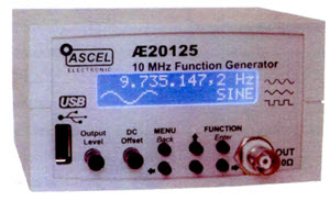
This month's giveaway is a 10 MHz function generator - or, rather, a bag of parts that can be assembled to be a function generator. I bought this from eBay a couple of years ago and just haven't had time to put it together. It could be a great project to do with a young 'un. There is no plastic box, and I can only presume all of the components are included.
Enter via this link. |
||||
| AI Means "Ain't Intelligent" | ||||
I'm not sure where we are on the hype cycle for AI, but AI and IoT are increasingly paired. IEEE Spectrum and so many other publications offer a never-ending stream of articles about how AI is reshaping the world. And it has scored amazing successes. I have no doubt that we will be seeing an avalanche of applications for AI, and it will find its way into small embedded devices. One mind-blowing example of success is the AlphaZero chess-playing robot: this article is stunning. Gartner thinks that by 2022 AI will be part of 80% of IoT devices. A Google search on "IoT AI" gives 178 million hits. I have yet to see any surveys on the use of AI in the embedded space today, and I suspect only a tiny fraction of the systems we build currently use it. To go from around zero to 80% of all IoT devices in a mere three years seems a bit of a stretch. Many people conflate AI with "intelligence," which it is not. Wikipedia states: Intelligence has been defined in many ways, including: the capacity for logic, understanding, self-awareness, learning, emotional knowledge, reasoning, planning, creativity, and problem solving. Current AI systems, for all of their amazing capabilities, are basically pattern classifiers. They do mirror a lot of the human brain, which itself is partially an incredible pattern classifier that can extract meaning from the visual field and auditory inputs. But the "intelligence" we posses is what happens after that classification. I doubt AI, as it exists today, will gain the capacity for understanding, self-awareness, etc. Future incarnations may change that. Sans AI, we build systems by understanding the problem and constructing a solution whose operation is understood. AI reverses this paradigm: no one really knows how an AI system works. An ocean of coefficients selected not by design, but by training, emits answers. No one really knows why input A generated result X. Just like the brain. While the prospects of AI are fascinating and exciting, we need to consider the implications of the unknowability of how a particular AI system works. What inspired this is a thoughtful email from frequent correspondent Charles Manning:
Kent Beck, the inventor of eXtreme Programming, said "The larger the scale, the more you must rely on emergence," by which he meant "write enough code and a design will emerge from the code." That always makes me shudder. But is AI the manifestation of that philosophy? |
||||
| Minimal Debugging Strategies | ||||
Replying to my thoughts about using two GPIOs and I2C as a debugging tool, Dan Daly wrote:
On a side note: HP 16500s are still available on eBay. They are big beastly machines that could be configured to suck in more channels than most of us would need in a lifetime. Today, small USB logic analyzers have taken the world by storm. I see tons of teams using Saleae's. My favorite USB LA is the one from Intronix, which offers an amazing value proposition. ZeroPlus has a couple of great offerings as well. It can be tough to get information out of a tiny embedded system. Daniel McBrearty suggested the use of a very small printf() library which is freely available here. Several others wrote that they sent Morse Code out via a speaker to get a sense of what was going on. This is a pretty low-bandwidth solution, but it is a nice trick. Though some ham radio operators still use Morse, it is no longer required to get any amateur radio license. Once lighthouses transmitted their ID via low-frequency radio in Morse; sailors used the Morse to identify the lighthouse, and then took bearings on the signal to navigate. But even that is gone, now that we're expected to put all of our navigational hopes in GPS. So I wonder if there's any incentive anymore to learn Morse Code, and suspect it will go the way of the sextant, slide rule, and abacus. |
||||
| Knowing Hardware | ||||
Sarah Wang had some comments about my thinking that firmware folks should engage in at least some of the hardware aspects of this field:
John Taylor agreed:
|
||||
| Debounce Code | ||||
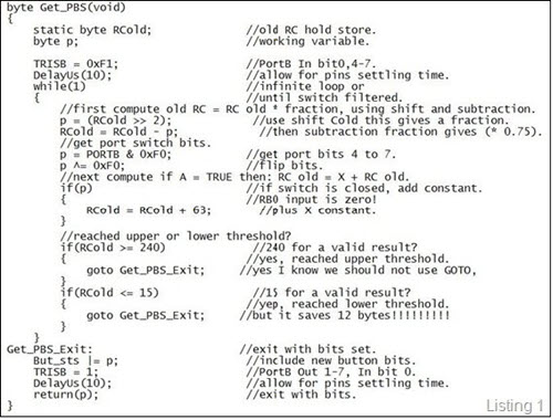
There's a never-ending interest in debouncing contacts; my article on the subject gets downloaded many thousands of times per month. Andrew Kollosche sent in his debounce solution: I came across an article, "Contact-debouncing algorithm emulates Schmitt trigger" published in EDN magazine, by Elio Mazzocca, Technical Consultant, Adelaide, South Australia (ref 1). In what could be described as a software Resistor-Capacitor (RC) Digital Filter algorithm, written in assembler for the ATmega8 microcontroller. Mazzocca states "This debouncing algorithm is effective because it 'remembers' past inputs transitions and assigns a 'weight' to each transition depending on how long ago it occurred". I found another web reference to a similar algorithm, this time written in 'C' code, called "Debouncing Switches" from The Department of Electrical and Computer Engineering, Oregon State University (ref 2). The tutorial declares, "This Digital filter mimics an analog RC filter, with a first-order recursive low pass filter. It has good EMI filtering, quick response. With a nearly continuous output like an analog circuit". The digital filter features appeared to fit my purpose so I put it to work on my switch problem. In my case removing the Schmitt Trigger Flag feature as I needed auto-repeat function (listing 1). While the basic algorithm worked much better than my previous de-bounce attempts it was still occasionally sporadic. I tried variations to the algorithm applying negative feedback and hysteresis, all to no avail.
Next I tried changes to the time-constant. Mazzocca stated in his article the algorithm could also use other time-constants (tc) 7/8+1/8 or 15/16+1/16 up to 63/64+1/64. So I started experimenting with some code and soon found the lower threshold point rose from 15 to 63 as the time-constant decreased. This was a problem at 63/64+1/64 where the 1/64 value was 3 and the lowest threshold count value was 63. The function exited before it could do any work. To solve this I added the following lines of code: else //if input = FALSE then: RCold = RCold – 1.
{ //makes all the difference.
if (RCold) //must be positive!
RCold = RCold - 1; //subtract constant 1/128th.
}
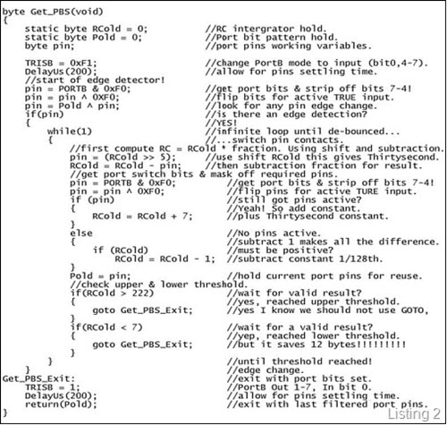
Even changing time-constants didn't fully solve the de-bounce problem. Still getting the very occasional contact bounce, enough to be annoying. I felt the algorithm needed a better way of being triggered into action and only when necessary i.e. change of switch state. I remembered an article titled "Debouncing Switches and Encoders" by John Youngquist published in The Embedded Muse, Issue Number 292, (ref 3). Youngquist declared his function, "requires only 3 instructions and one status storage byte. It can be triggered by positive or negative transitions. It is a simple logical edge detector". The code was simple enough, first remember the last switch state (open or closed, i.e. 0 or 1). Next get the current switch state and use the logical XOR operator with last switch state to see if there has been any change of state? If not exit with the last known state of the switch. Otherwise process new switch state using the Resistor-Capacitor (RC) Digital Filter algorithm. Result of the RC filter is then saved as the last switch state (listing 2).
Its fast, on a PIC16F88 @ 2MHz with no change to input switch, the function runs in 50us with delay of 400us for port configuration changes. When edge detected the RC filter takes 9ms to filter input using time-constant of 1/32nd. Not bad eh!! I've nearly worn out the switches trying to get false triggers, so far this new variation of the filter function appears to be working quite well. Final code: /*
* Switch De-bounce using Edge Detection & Resistor-Capacitor Digital Filter.
*
* This Digital filter mimics an analogue RC filter with first-order
* recursive low pass filter. It has good EMI filtering and quick response,
* with a nearly continuous output like an analogue circuit.
*
* Based on Elio Mazzocca, Contact-debouncing algorithm emulates Schmitt trigger.
* Based on Oregon State University, Debounce switches algorithm.
* Based on John Youngquist, Debouncing Switches and Encoders.
* Version by Andrew M. Kollosche, 2015-2018.
*
* Expects switch contact to be on PORTB bit 0 to ground or logic zero.
* Filter time constant: 1/32nd.
*
* Time-Constant TC, UTH, LTH, Approx execute times on a PIC16 @ 2MHz.
* No change - - 50us. Ideal for Superloop operation.
* Quarter 63, 242, 15, 1ms.
* Eight 31, 238, 12, 2ms.
* Sixteenth 15, 230, 10, 3ms.
* Thirty-second 07, 215, 07, 9ms.
* Sixty-forth 03, 184, 03, 15ms.
* Note: Thresholds count for each RC time-constant,
* is calculated on 3 time-constants or for Upper threshold is 96% and
* 3% for Lower Threshold.
*
* Enter - void.
* Exit - 0 – no contact. 50us.
* 1 – contact. 9ms.
*/
byte ED_RC_DFL(void)
{
static byte RCold = 0; //RC integrator hold.
static byte Pold = 0; //port bit pattern hold.
byte pin; //port pins variable.
 //start of edge detector!
  pin = PORTB & 1;                       //get port bits & strip off bit 0!
  pin = pin ^ 1;                         //flip bits for active true input.
  pin = Pold ^ pin;                      //look for pin edge change.
  if(pin)                                //is there an edge detection?
    {                                    //YEAH! Now make sure its a real contact!
    while(1)                             //start infinite loop or until ...
      {                                  //... switch contacts are de-bounced.
      //first compute RCnew = RCold * fraction. Using shift and subtraction.
      //  temp = (RCold >> 2);           //use shift RCold this gives Quarter.
      //  temp = (RCold >> 3);           //use shift RCold this gives Eight.
      //  temp = (RCold >> 4);           //use shift RCold this gives Sixteenth.
      pin = (RCold >> 5);                //use shift RCold this gives Thirty-second.
      //  temp = (RCold >> 6);           //use shift RCold this gives Sixty-fourth.
      RCold = RCold - pin;               //then subtraction fraction for result.
      //get port switch bits & mask off required pins.
      pin = PORTB & 1;                   //get port bits & strip off bit 0!
      pin = pin ^ 1;                     //flip bits for TRUE input.
      if (pin)                           //got any pins?
        {                                //Yep! So add constant.
        //      RCold = RCold + 63;      //plus Quarter constant.
        //      RCold = RCold + 31;      //plus Eight constant.
        //      RCold = RCold + 15;      //plus Sixteenth constant.
        RCold = RCold + 7;               //plus Thirty-second constant.
        //      RCold = RCold + 3;       //plus Sixty-forth constant.
        }
      else                               //Zero pins input.
        {                                //subtract 1 makes all the difference.
        if (RCold)                       //must be positive.
        RCold = RCold - 1;               //subtract constant 1/128th.
        }
      Pold = pin;                        //save filtered port pins for reuse.
      //check upper & lower threshold.
      if(RCold > 215)                    //got a valid result?
        {                                //Yes, reached upper threshold.
        return(pin);                     //exit switch closed!
        }
      if(RCold < 7)                      //wait for a valid result?
        {                                //Ok, reached lower threshold.
        return(pin);                     //exit with segment bits.
        }
      }                                  //until threshold reached!
  }                                      //edge change.
   return(Pold);                         //exit with last filtered port pins.
}
References: 1) Elio Mazzocca, Technical Consultant, 2) Oregon State University, |
||||
| This Week's Cool Product | ||||
Microchip's new MCP6V51 op amp is advertised as a zero-drift (it's actually very low drift, ±15 uV and ±36 nV/°C), 140 dB open-loop gain, 134 dB PSRR and 135 dB CMRR device. It will take power supplies from 4.5 to 45 volts. There are built-in EMI filters. With a gain-bandwidth product of 2 MHz it's not particularly speedy, but is targeted at high-precision DC and low-frequency measurements. A buck each in 10,000 lots, $1.36 in singles. Note: This section is about something I personally find cool, interesting or important and want to pass along to readers. It is not influenced by vendors. |
||||
| Jobs! | ||||
Let me know if you’re hiring embedded engineers. No recruiters please, and I reserve the right to edit ads to fit the format and intent of this newsletter. Please keep it to 100 words. There is no charge for a job ad. |
||||
| Joke For The Week | ||||
Note: These jokes are archived here. Not a joke; perhaps this section should be "Funny of the Week." Chris Shore, responding to the comments in Muse 364 about watchdog timers, wrote: Very early in my career (so late 80's I guess) I was involved with developing a radio switching system. We bought in a multi-channel digital switch from a UK supplier and incorporated it. It had a green LED on the front of the box labelled "Watchdog" which flashed at a steady, slow and reassuring rate all the time the machine was operating. One day, we managed to make it crash and noticed that the watchdog was still flashing. Curious, we took the lid off and discovered that the LED was wired to the output of a 555 timer connected straight across the power rails. No wonder it always flashed! |
||||
| Advertise With Us | ||||
Advertise in The Embedded Muse! Over 28,000 embedded developers get this twice-monthly publication. . |
||||
| About The Embedded Muse | ||||
The Embedded Muse is Jack Ganssle's newsletter. Send complaints, comments, and contributions to me at jack@ganssle.com. The Embedded Muse is supported by The Ganssle Group, whose mission is to help embedded folks get better products to market faster. |


Follow @jack_ganssle