|
|
||||
You may redistribute this newsletter for non-commercial purposes. For commercial use contact jack@ganssle.com. |
||||
| Contents | ||||
| Editor's Notes | ||||
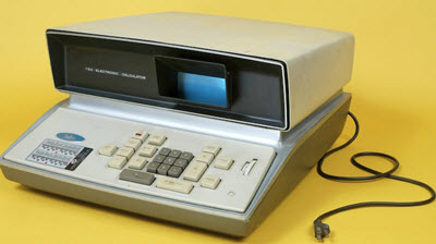
Happy New Year to all Muse readers! I'm not sure what happened to 2017, which flew by in a nanosecond, but wish for a happy and bug-free 2018 for us all. Discounted Better Firmware Faster on-site seminars in Europe: I'll be at the Embedded World show in Nuremberg February 27 to March 1. Being already in Europe, I will be offering on-site versions of this class in Europe for a reduced price shortly before and after the show. If interested, drop me an email. A number of people sent a link to this wacky and fun video about a Friden calculator that uses delay-line memory.
When I was a young 'un the company my dad worked for had several of these. When one pressed the "square root" the button would lock down for several seconds until a result appeared. Later, I was given one after it failed, and remember the oceans of transistors in the thing. Now I wish I had saved it. There's some interesting technical details here. These sold for around $2k in 1965, which is $16k in inflation-adjusted dollars. Imagine paying that for a calculator that can only do the four basic arithmetic functions plus square root! Possibly the lesson we can take from this - and so much other - personal technology is that all of these electronic gadgets will disappear into the one thing we all carry: our smart phones. GPS? Nope, it's in the phone. MP3 player? Ditto. Calculator, camera, compass: they were all absorbed into phones. |
||||
| Quotes and Thoughts | ||||
"No product of human intellect comes out right the first time. We rewrite sentences, rip out knitting stitches, replant gardens, remodel houses, and repair bridges. Why should software be any different?" - Ruth Wiener |
||||
| Tools and Tips | ||||
Please submit clever ideas or thoughts about tools, techniques and resources you love or hate. Here are the tool reviews submitted in the past. Rob Vice isn't pleased with the latest version of IAR's IDE. I have not used version 8.x, but have always liked their tools. I sent this to IAR and asked for comments three weeks ago, and as yet have not gotten a reply. Rob's comments:
|
||||
| This Month's Giveaway - a Bench Scope | ||||
This month's giveaway is the Siglent SDS1204X-E four-channel, 200 MHz digital oscilloscope I review later in this issue. The contest will close at the end of January, 2018.
Enter via this link. |
||||
| Early Electronics | ||||
Charles Manning takes issue with my comments that electronics started with the invention of the vacuum tube:
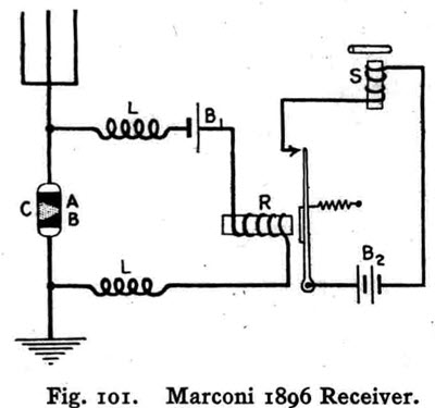
Coherers were antecedents to diodes and other mechanisms to "detect" radio signals (extract the signal from the modulated carrier wave). Despite being involved in electronics for over half a century, I have never seen one in person. The Wikipedia article says it best: "The basis for the operation of the coherer is that metal particles cohere (cling together) and conduct electricity much better after being subjected to radio frequency electricity. The radio signal from the antenna was applied directly across the coherer's electrodes. When the radio signal from a "dot" or "dash" came in, the coherer would become conductive. The coherer's electrodes were also attached to a DC circuit powered by a battery that created a "click" sound in earphones or a telegraph sounder, or a mark on a paper tape, to record the signal. Unfortunately, the reduction in the coherer's electrical resistance persisted after the radio signal was removed. This was a problem because the coherer had to be ready immediately to receive the next "dot" or "dash". Therefore, a decoherer mechanism was added to tap the coherer, mechanically disturbing the particles to reset it to the high resistance state." Also from Wikipedia, here's the circuit for a Marconi receiver:
The coherer is labeled "C". The decoherer is not shown. In many cases that was a mechanical thing, rather like a doorbell, that tapped the coherer. I guess today we would need a couple of million transistors... |
||||
| VDC Survey Results | ||||
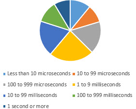
VDC completed their survey of the embedded space and sent a copy to me. I believe the results are not generally available, but they gave me permission to cite factoids I found interesting. Some 70% of respondents have at least some hard real-time deadlines. Distribution of real-time responses is:
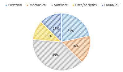
20% of us have sub-100 μs deadlines. Software consumes more time than any other aspect of a project:
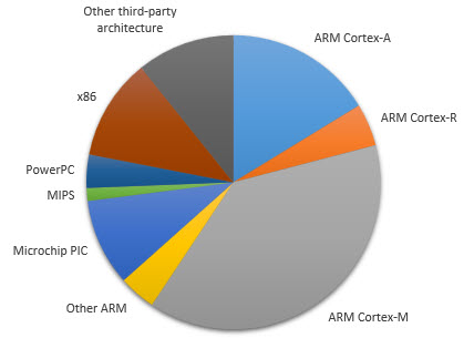
The mean schedule from inception to delivery is 15 months; the median is 12, exactly the same as in their 2011 survey. The mean size of the project is 233,000 source lines, with a median of 20,000. I'm not entirely sure how meaningful this is, as there are many ways to count lines of code. If Linux was used, did respondents include those millions? The wide disparity between mean and median suggest there are a ton of very small projects. How much code does a smart toothbrush need? The biggest reasons for slipped schedules are: technical obstacles, changes in specifications, complexity of the application/technology, emergence of higher priority projects, lack of manpower, customer changed requirements, and unrealistic schedules. In the first year after a product is shipped, the average number of bugs discovered is 67. The median is 5, so some seriously-buggy code is out there. The mean time to fix each bug is 445 hours, with a median of 30 hours. That's interesting, as it lends credence to the observation that bug fixes cost orders of magnitude more in the field than in development. The ARM Cortex rules:
| ||||
| New Siglent 4-Channel, 200 MHz Oscilloscope | ||||
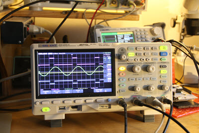
Siglent has some new scopes that are worth looking at. They sent me one and I'm impressed. It can be yours - I'm giving it away at the end of this month. Enter the contest here. Two and four channel models are available, with bandwidths of 100 MHz and 200 MHz. I'll delve into the 200 MHz four-channel SDS1204X-E, as that's the one I looked at.
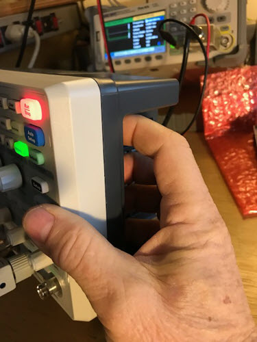
First, overall impressions: the screen is bright and the text is small but crisp. The scope is a tiny thing at 312 mm L, 134 mm W, 150 mm H and 2.5 Kg. Buttons and knobs all have a solid feel. There is a fan but it's pretty quiet - I play the local classical station all day at a low volume and the fan didn't interfere with the music. Both the left and right side of the unit are recessed, providing very nice handholds - see this picture:
Modern scopes are so small and lightweight that you need to hang on to them when pushing a probe's BNC connector in, which is why I like these handholds. My main scope lives in one place on the bench, so I screwed a piece of wood to the bench behind it so it doesn't move when connecting a probe. A knob is labeled "Intensity Adjust". This is also the "universal knob." Many digital scopes have a universal control, which is used to select options after pressing one of the other controls. So press Trigger Setup and the universal knob selects (among other things) the trigger channel. I expected the Intensity Adjust to select the traces' brightness - it doesn't. You have to find a submenu of the Display Persist control, and then the Intensity Adjust knob does what you'd expect. This shouldn't have surprised me as their much more expensive SDS2304X works the same way, though I felt the adjustment was smoother on the newer model. I think the universal knob is too sensitive; it's easy to overshoot the desired option. But the universal knob on every scope I've tested feels too sensitive, so maybe it's me. The sample rate is a little confusing at first. The datasheet says "four channel series have two 1 GSa/s ADCs. When all channels are enabled, each channel has a maximum sample rate of 500 MSa/s. When a single channel per ADC is active, it has sample rate of 1 GSa/s". That is quite true if read carefully. But when I first started playing with the unit, prior to reading the spec, I was a bit confused since the screen displays "1 GSa/s" when only channel 1 is enabled, but falls to 500 GSa/s when channels 1 and 2 are both on. However, by turning 2 off and 3 on the display shows 1 GSa/s. Channels 1 and 2 share an ADC, and 3 and 4 share the other ADC. The same effect is manifested for the memory depth. There are two 14 million-point memories, one for channels 1&2 and another for 3&4. So, if two channels from the same ADC are selected the memory depth is 7 million points. Still, that's a ton of data.
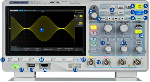
Notice that there's only one set of vertical controls, rather than one per channel. I guess they had to do this to keep costs down and the form factor small. Some years ago I was put off by an inexpensive Rigol scope due to the same shared controls. Note, in the picture, the Siglent has four channel selection buttons, labeled 1 to 4. You press one to select a channel, and the vertical gain and position controls work for that channel. While I much prefer having separate controls, this actually works pretty well. One must, though, get used to looking at the screen (see the following screen shot) to see which channels are enabled (in the picture channels 2 and 3 are on, and the trigger is from CH2). It took a while for this old scope user to get used to this; I found myself often twisting the horizontal knobs thinking they were the second channel's vertical controls.
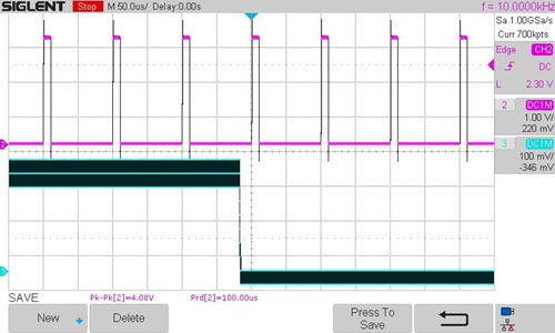
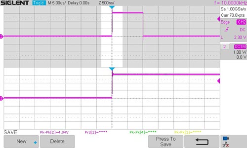
Also note that the upper right side of the screen shows triggering info and the frequency of the signal on the trigger channel. All of the rotating knobs can be pressed in. In the case of the vertical gain this lets you select a "fine" level with much more resolution than the usual 1-2-5 sequence. The position knobs, when pressed, returns the displayed signal to the (vertical) middle position. Depressing the horizontal sweep control, though, pops up another view of the signal. Now, rotating the control blows up a portion of the waveform. For instance:
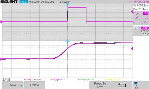
The non-grayed part of the top trace represents the span of the bottom trace; the bottom trace is a zoomed-in version of that span. Cranking the horizontal control even more and the span goes down, but the bottom trace now shows much more detail about the rising edge of the pulse:
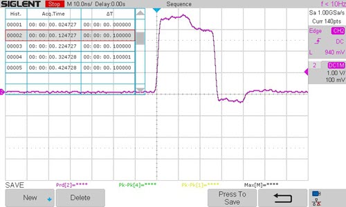
In this mode the horizontal position control pans the bottom trace span left or right through the top trace. This feature isn't uncommon on digital scopes; I use it all of the time and wouldn't buy a scope without it. The vertical channels can go as low as 500 μV/division, and the horizontal down to 1 ns/div. The latter seems to be pushing things for a 200 MHz scope, but given the 16 digital channels option, that 1 GSa/s makes sense. One feature that is occasionally very useful is segmented acquisition. I think Agilent first came up with this idea some years ago. I don't use it often but it can be a real lifesaver. On the SDS1204X-E the name "segmented" is sometimes conflated with "sequence," but the idea is that you can divide acquisition memory up into little chunks. Each trigger fills a chunk. If a triggering event happens infrequently compared to the sweep rate, conventional memory would fill after the event occurred the first time. In segmented mode, the acquisition stops when a chunk is filled, then restarts using the next buffer when the trigger happens again. You can acquire a lot of events, even if they happen far apart in time. The memory can be divided into as many as 80,000 chunks. In the following example the signal is a 28 ns pulse that comes ten times per second. Sweep rate is 10 ns/div. Sans segmented/sequence mode the first pulse would have completely filled memory. But here I've divided the buffer into 5 chunks. Chunk number 2 is the displayed pulse; the universal knob lets you select which chunk to display. The numeric table gives info about each segment:
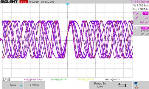
The SDS1204X-E has all of the usual triggering modes. On some of these inexpensive Chinese scopes I've found that at high sweep rates the triggering can be a tiny bit erratic - the signal might jump left and right a pixel or two. This unit does not have that problem. A few trigger modes might be unfamiliar, especially if you haven't used a modern instrument. Pulse trigger starts acquisition if the input pulse is longer or shorter than a specified amount. Or, it can trigger only if a pulse width is inside or outside a user-selected range. A window trigger (poorly described in the manual, but the one-line of help on the instrument makes things very clear) triggers when the signal's amplitude leaves a selected range (the "window"). The pattern trigger starts acquisition based on AND, OR, NAND and NOR combinations of the signals from the four channels. The scope can trigger on specific I2C, SPI, UART/RS232, CAN and LIN patterns; it will also decode those signals, showing the acquired data in hex. I think these, particularly I2C, makes for a great debugging resource. Dedicate two GPIO pins to this, write a simple I2C bit banger, and you can send all sorts of debugging info to the scope. Think in terms of a sort of limited embedded printf(). Automatic measurements abound. The scope will give numbers for just about anything you can conceive of. Digital scopes have spoiled me, and I always enable some of the metrics. Who wants to count divisions anymore? Color "temperature" display modes are increasingly common today. With a changing input signal, the SDS1204X-E can use colors to show the most common signal levels:
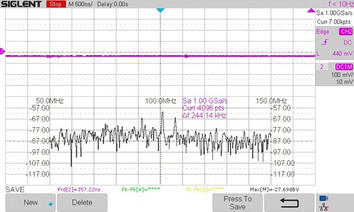
I think that could be really useful for eye diagrams, but the scope's 200 MHz bandwidth probably precludes it from most of that sort of work. My fancy Agilent has a built-in self-calibration mode, which requires connecting all of the inputs to the waveform generator using a profusion of BNC cables. The Siglent also self-cals, but you don't have to connect anything; some magic in the box does the work autonomously. If you have a Siglent arbitrary waveform generator, the scope can control it and sweep a sine wave. Feed that through a circuit under test, and the scope can display a Bode plot of the circuit's amplitude and phase response. That is actually a pretty cool feature. Normally I'd use a spectrum analyzer and its tracking generator output to characterize a circuit's behavior in the frequency domain, but the SDS1204X-E's Bode plots will eliminate the need for the SA for lower-frequency work. (Most SA's operate into the GHz range). In addition to Bode plots, the Siglent can do various math on the signals, including FFTs. Now, I'm not a huge fan of scope FFTs as the instruments just don't have the sensitivity and resolution of a spectrum analyzer, nor do they generally have peak detectors and the like. Just for fun I connected an antenna - a half-meter of wire - to the scope's input, cranked the vertical gain way up, and set it to look at the FM radio band. Sure enough, right in the center of the display there's a peak at 100.7 MHz, which is the frequency of the strongest FM station we get in our rural neighborhood. The datasheet says the scope's FFT uses one million points, and it does look good.
Finally, the unit has a built-in web server. Connect it to your PC (heck, with the Wi-fi option I guess you could connect it to a phone) and the PC/phone can completely control the scope. The 222 page user manual (provided on disk) is actually pretty good for a Chinese instrument. The scope's specs are here. The model I tested retails for $759, which I consider a true bargain. A four-channel 100 MHz version is $499. Back in the 1960s "Made in Japan" meant cheap junk. Things changed, and that country learned to produce very high-quality products. "Made in China" had - and often still has - the same 1960's cachet. But I'm blown away by the advanced engineering and quality of manufacturing exhibited by this and some other Chinese test equipment. |
||||
| Jobs! | ||||
Let me know if you’re hiring embedded engineers. No recruiters please, and I reserve the right to edit ads to fit the format and intent of this newsletter. Please keep it to 100 words. There is no charge for a job ad. |
||||
| Joke For The Week | ||||
Note: These jokes are archived at www.ganssle.com/jokes.htm. Steve Land's joke submission last issue was: I'd tell you a UDP joke, but I'm not sure you'd get it. Here's the opposite joke: "Hi, I'd like to hear a TCP joke." |
||||
| Advertise With Us | ||||
Advertise in The Embedded Muse! Over 27,000 embedded developers get this twice-monthly publication. . |
||||
| About The Embedded Muse | ||||
The Embedded Muse is Jack Ganssle's newsletter. Send complaints, comments, and contributions to me at jack@ganssle.com. The Embedded Muse is supported by The Ganssle Group, whose mission is to help embedded folks get better products to market faster. |