|
||||
You may redistribute this newsletter for non-commercial purposes. For commercial use contact jack@ganssle.com. To subscribe or unsubscribe go here or drop Jack an email. |
||||
| Contents | ||||
| Editor's Notes | ||||
Over 400 companies and more than 7000 engineers have benefited from my Better Firmware Faster seminar held on-site, at their companies. Want to crank up your productivity and decrease shipped bugs? Spend a day with me learning how to debug your development processes. Attendees have blogged about the seminar, for example, here, here and here. |
||||
| Quotes and Thoughts | ||||
"The problem with object-oriented languages is they've got all this implicit environment that they carry around with them. You wanted a banana but what you got was a gorilla holding the banana and the entire jungle." Joe Armstrong |
||||
| Tools and Tips | ||||
Please submit clever ideas or thoughts about tools, techniques and resources you love or hate. Here are the tool reviews submitted in the past. Tip: I look at a lot of eval boards from various vendors. They mostly have one nasty thing in common: the lack of a big ground pin. It's common to connect an instrument to these boards, like a scope, but where will you clip the probe's ground lead? Some have ground available in a 0.1 x 0.1 header, which is great for a logic analyzer connection, but less so for an alligator clip. When designing a board provide at least a nice through-hole via where one can solder a wire (I use an RC07 resistor) to provide a nice big ground. |
||||
| Freebies and Discounts | ||||
Jason Long is donating three copies of his brand new book Embedded in Embedded for this month's giveaway. A short review was in the last Muse. Enter via this link. |
||||
| Review of the Minidso | ||||
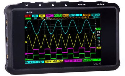
A lot of test equipment parades through the lab here. Some state-of-the-art gear is to die for, with specs that will stoke a grown engineer's desire. Some is just cool; for example, one of the coolest scopes I've looked at is Gabotronix Xprotolab. With a 200 KHz bandwidth and tiny screen it's not good for much as an instrument, though I could see embedding it in a device. But, how can one not smile at this thing? Recently Chinese company Minidso sent me their DS213 mixed signal scope, which definitely is in the "cool" category. Smaller than an iPhone it has two analog channels, two digital channels, and a waveform generator. The web site is a quintessential engineer's bit of marketing: it's long on what's inside the box (Cortex M3, FPGA, etc.) but specs and features are somewhat downplayed.
Battery operated, it charges over a USB connection. The battery holds a charge for a surprisingly-long time. On Amazon it's $230. Other web vendors seem to price it at $159 You're not going to fit BNC connectors to this little thing. It appears to use MCX connectors, which means special scope probes are needed. Two are included, so if you want to use all four (analog + digital) channels you'll have to buy more or cobble a solution together. First, the specs:
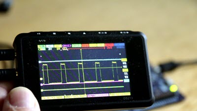
Though the bandwidth is rated at 15 MHz I found the -3 dB point to be more like 10 MHz. Normally I'd fit 500 MHz probes to see if the probes or the unit were the limiting factor, but with the unusual connectors that wasn't possible. They tell me the manual is a work in process. At this moment it's (barely) adequate. I was never able to figure out how to change the triggering channel. With so little space for controls the unit's operation is a bit unusual. Two main scroll wheels on the top do most of the heavy lifting. One scrolls between menu items (like selecting a particular channel); the other selects the operation within that item, for instance, setting a selected channel's gain. The screen is too small to implement a touchscreen, so this interface makes sense. It's unusual, though, so I filmed a video to show how they operate (click on the picture to download the 7 MB video):
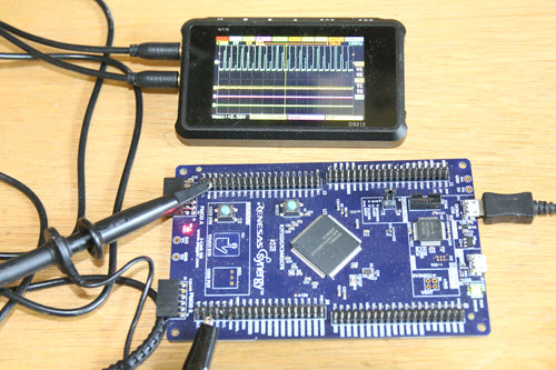
All of the usual scope features are supported, including the ability to add or subtract the analog channels, and to AND or OR digital inputs. You'd expect this to trigger on the usual leading or trailing edges as well as voltage levels, which it does, but it'll also trigger on pulse widths greater or less than a selected time. The waveform generator also uses an MCX connector. It will generate 3 volt square, sine, triangle or sawtooth waves between 10 Hz and 20 KHz (square waves will go to 8 MHz). All sorts of measurements are possible, like peak-to-peak as well as RMS voltages. Two cursors provide data in the time domain. Unlike a bench or USB scope, the Minidso can lay on the bench right next to the device being probed, so you don't have to look up from your work to see the signal. I really like that.
Due to its small size and feature set this is a cool (and fun!) little scope. With a limited bandwidth it's not particularly useful in an engineering lab but students and hobbyists would find value in it. The specs/price ratio compares very favorably with a lot of entry-level USB scopes. |
||||
| LabRecon Review | ||||
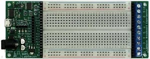
Joe Barbetta of LabRecon sent me his product, the BreadBoard Experimenter (BBE), for evaluation. I had tried to make sense of this from the web site with only partial success. LabRecon is, like Gaul, divided into three parts: there's the LabRecon IC itself, the BBE, and a PC-hosted software package that drives the BBE. The IC (datasheet here) is an interface to the world. It includes 8 analog inputs, 4 PWM outputs, 4 servo outputs, 2 stepper motor outputs, 7 PIOs, a quadrature encoder input, 2 counter inputs and an I2C interface. RS-232 (5 volt levels) interfaces the IC to other logic if you want to embed the IC in your product. An interesting mix of peripherals, but not unlike those in many MCUs. The BBE is a breadboard that includes the LabRecon IC and a USB connection to a host PC:
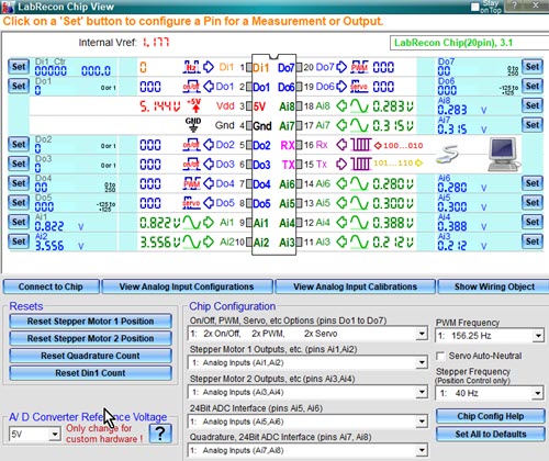
And then there's the software which interfaces the PC to the BBE. With a few clicks the following window appears:
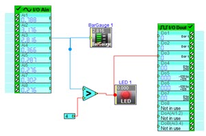
This shows all of the signals from and to the chip. It updates at a blinding rate. But that's not the interesting part of this product triad. Displaying data is nice enough, but what if you want to process it? That's where LabRecon shines. For it's rather like a schematic capture package, except that the resulting schematic actually runs. The software simulates the actions drawn on screen. A simple example: I designed this circuit which reads an analog input to the BBE, displays it in a bar gauge, and compares the value to a fixed 4 volts. If above 4 the virtual LED comes on:
The comparator also goes to a digital out. I could observe the signal on the BBE with a scope. With a slow sine wave applied to the analog input on the BBE the PC displays:
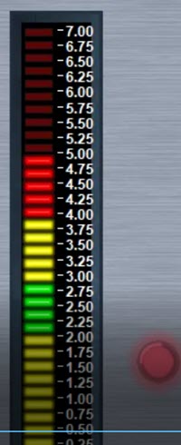
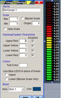
Click on image to run the video So the "circuit" is a simulation using real-world inputs and outputs. The bar gauge and LEDs are widgets dragged onto the screen from a large library. Each widget has tons of configurability: for instance, the bar graph's range, and ranges where the colors should change to display cautions and the like. For instance (the left is the properties window that appears during a right-click on the widget; it goes away after you've set the widget up. The right is the widget):
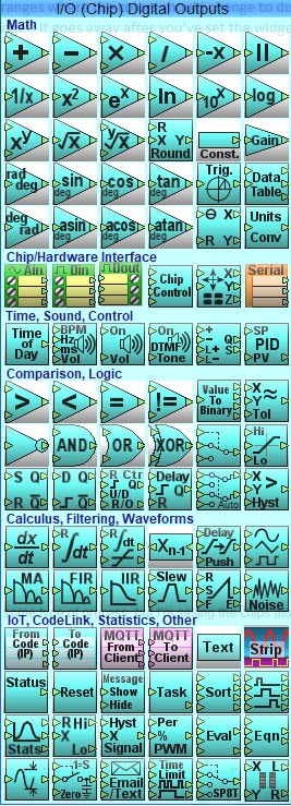
Oh, and that bar gauge, LED and comparator? They, too, come from a big library of choices:
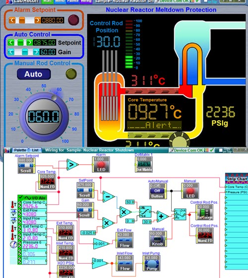
That's quite a selection! The simple circuit shown above barely taps the power of the product. A lot of pre-built projects are included; one is a shutdown simulator for a nuclear reactor:
The circuit and control panel were all created in LabRecon, and actually runs using simulated inputs. There's far more than I can do justice here. For instance, a Measurement Wizard supports some 500 commercial, real-world, sensors one can add to the BBE. There's some quirkiness: if you move a component that's wired to something else, the connection is properly maintained, but the wire will sometimes route oddly, like inside a component. And it takes a bit of time to get familiar with the tool as there's no manual (though there are a number of how-to .PDFs). Update rates are slow. The analog is spec'd at 2 Hz and digital outputs at 20 Hz. Joe tells me it's targeted at engineers, hobbyists and educators who want to experiment or monitor/control a process. The software is free, the BBE $80, and chips $20 each (one is included with the BBE). Joe is running a Kickstarter to enhance the product which should be running about the time this Muse is released. Can't afford LabVIEW? Here's a very cool alternative. I intend to hang onto it for running occasional experiments. |
||||
| Plane Crashes and Feedback Loops | ||||
Photos of cats, celebrities, and disasters flood the internet. But to me, this image is one of the most compelling I've seen:
It's a chart showing an enormous plunge in airplane accidents while the number of trips has exploded. I've had this for a number of years and don't remember where it's from, but pull it out from time to time to ponder the implications. The 737 MAX debacle has many terrified of flying, but the 100,000 routine flights per day get no press. Air travel is sort of bizarre: at 40,000 feet doing 500 knots, air pressure of 3 PSI, gigantic turbines rotating at 12,000 RPM - it's stunning that an aircraft works at all. But it does, with astonishing reliability. Think about that chart: it defies conventional wisdom. In most human endeavors increasing exposure to a hazard means more failures. But air travel is different, and for an important reason: every accident is investigated, causes are determined, and something is changed so that accident won't happen again. Training, maintenance, procedures, even design of the system: the culprit is found and remedial action taken. Mistakes are used to improve the system. A fascinating 1996 article about the Space Shuttle's software engineering process is a must-read for all firmware developers and their managers. The main takeaway is that the Shuttle team created near-perfect code by creating a process that yields near-perfect code. When an error is detected it's fixed, of course, but the team tries to understand how the mistake appeared in the first place. They then fix the process so that error won't happen again. The result: about one bug per 400K lines of code. That's nearly three orders of magnitude better than most good-quality firmware. We all make mistakes and bugs will always be an element of creating software, which is probably the most complex engineered product in history. But great teams will figure out how errors creep in and patch the process. This feedback loop helps teams evolve to a higher level of perfection. |
||||
| How Much Time Spent in Design | ||||
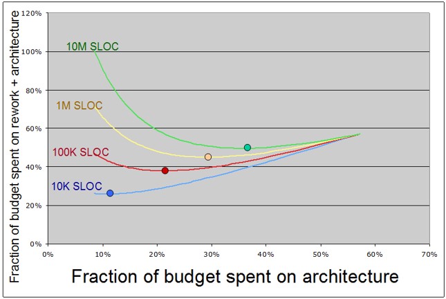
I'm often asked how much time should be devoted to a system's design. Plenty of web sites have ratios for effort v phase of the development lifecycle. But these are too simplistic. Some trivial problems might require a minute's thinking; more complex systems might demand a tremendous amount of design. The article about the Shuttle's code cited above claims they devoted a third of the engineering effort to design and planning. That mirrors a JPL study of spacecraft software:
From NASA's Flight Software Complexity Briefing (CL#08-3913) This data shows that too little time designing means lots of rework. The sweet spot on the four curves is the minimum point denoted by the colored bubble. The old aphorism holds true: "If you think good design is expensive, try bad design." |
||||
| This Week's Cool Product | ||||
Does your product already have a microphone and speaker? If so, there's a new comm mechanism that is rather intriguing. Chirp (2020 update: the link no longer works and it's not clear this product is available any longer) sends messages via audio. At 17 - 20 KHz the frequencies are inaudible to adults. Bandwidth is low - figure no more than 1 kb/s. They claim potential ranges of up to 100 m, but I imagine that the presence of walls and soft furniture could lower that. The graphs they provide show that even at 10 m the bandwidth drops by an order of magnitude. It's an interesting option in RF-restricted environments, and no FCC approval is needed. I once bought an Annoy-a-Tron, an device that emits a number of annoying sounds. One of the modes didn't work: I couldn't hear a thing. But in minutes my at-the-time teenager came in and asked: "What's that awful noise?" It was a 17 KHz tone. Note: This section is about something I personally find cool, interesting or important and want to pass along to readers. It is not influenced by vendors. |
||||
| Jobs! | ||||
Let me know if you’re hiring embedded engineers. No recruiters please, and I reserve the right to edit ads to fit the format and intent of this newsletter. Please keep it to 100 words. There is no charge for a job ad.
|
||||
| Joke For The Week | ||||
Note: These jokes are archived here. An electrician arrived home at 3 AM. His wife asks: "Why are you insulate?" He replied: "Watt's it to you, I'm ohm, aren't I?" |
||||
| About The Embedded Muse | ||||
The Embedded Muse is Jack Ganssle's newsletter. Send complaints, comments, and contributions to me at jack@ganssle.com. The Embedded Muse is supported by The Ganssle Group, whose mission is to help embedded folks get better products to market faster. |