Go here to sign up for The Embedded Muse.
The Embedded Muse Logo The Embedded Muse
Issue Number 384, October 21, 2019
Copyright 2019 The Ganssle Group

Editor: Jack Ganssle, jack@ganssle.com

   Jack Ganssle, Editor of The Embedded Muse

You may redistribute this newsletter for non-commercial purposes. For commercial use contact jack@ganssle.com. To subscribe or unsubscribe go here or drop Jack an email.

Contents
Editor's Notes

Express Logic

Over 400 companies and more than 7000 engineers have benefited from my Better Firmware Faster seminar held on-site, at their companies. Want to crank up your productivity and decrease shipped bugs? Spend a day with me learning how to debug your development processes.

Attendees have blogged about the seminar, for example, here, here and here.

Jack's latest blog: On Retiring

Quotes and Thoughts

You'll always get the good news; it's how quickly your get the bad news that counts. Harvey Mackay

Tools and Tips

SEGGER Embedded Studio The leading cross platform IDE

Please submit clever ideas or thoughts about tools, techniques and resources you love or hate. Here are the tool reviews submitted in the past.

Bryce Deary likes Ceedling:

Was surprised to see no one had mentioned the ceedling tool for doing unit testing.  https://github.com/ThrowTheSwitch/Ceedling
I have been using this tool to unit test embedded systems, or more appropriately unit testing before moving to target hardware so I am confident the code is generally correct and my target debugging will be more limited to target related issues.
Ceedling is an automation tool for the unfortunately name Unity framework which was explained in the great book Test-Driven Development for Embedded C (for which you wrote the forward). Ceedling makes using Unity and associated mocking frameworks super easy.  This point is in my mind the most important. People by now know unit testing and test driven development is a good idea, but if it is hard to do or maintain they won't stick with it.  There is a better explainer at http://www.throwtheswitch.org/ and a very good explanation of using it in embedded at https://dmitryfrank.com/articles/unit_testing_embedded_c_applications  and at https://www.embedded.com/modern-unit-testing-in-c-with-tdd-and-ceedling/ .   I have a gist with help for setting up ceedling on a Windows machine here https://gist.github.com/bd2357/b2d69ab18849c1e2f70959eef426ff09 . On Linux it is dead easy since gcc and ruby are often already installed.  

Joe Szedula had an idea about watchdogs:

The article "Great Watchdog Timers For Embedded Systems" states:

There's yet one more kink, though. Some tasks run so infrequently or erratically that any sort of automated profiling will fail. A watchdog that runs once a second will miss tasks that start only hourly. It's not unreasonable to exclude these from watchdog monitoring. Or, we can add a bit of complexity to the code to initiate a watchdog timeout if, say, the slow tasks don't start even after a number of hours elapse.

Rather than trying to monitor a slow task why not "speed it up" by inserting idle states into the task doing something like:

void the_task(void) {
   static unsigned  int idle_counter = 1;
   // execute task  every 100ms, only perform operation once every hour
   const unsigned  int idle_counter_max = 36000;
   idle_counter++;
   if (idle_counter  >= idle_counter_max) {
     idle_counter  = 1;
     // perform  task operation now
     ...
     } else {
       // task idle  state
     }
   Set_Alive(my_task_flag);
 }

The slow task will only perform it's assigned task once every hour but it's execution status can be checked once every 100ms. The cost for this implementation is a counter increment and an "if" statement.

I've used this in some of my embedded code so I could run the watchdog with a shorter timeout.

Clyde Shappee wrote that if you download a trial of OrCAD you get on their email list, and occasionally they offer a deep discount on that CAD tool.

Freebies and Discounts

This month's giveaway is an Amazon Echo Show 5.

Amazon Echo Show 5

Enter via this link.

A Low-Cost Performance Analyzer Upgrade

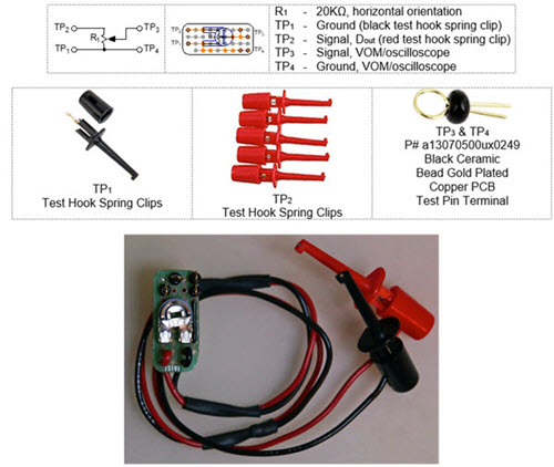
Joe Szedula, who contributed his thoughts on watchdogs (above), also had an idea for a poor-person's performance analyzer, derived from my thoughts on the subject here.

Inspired by:

  • Episode 12: How to Turn a $25 VOM Into a $10k Performance Analyzer
    https://www.ganssle.com/video/episode12-measuring-idle-time.html
  • eXtreme instrumenting https://www.embedded.com/electronics-blogs/break-points/4025673/eXtreme-instrumenting

Notes:

  • Rather than modifying the VOM as is suggested by both "Inspired by" URLs, I built this
    circuit so a potentiometer (R1) can adjust the VOM to read full scale deflection at 100% idle.
    Uses 1/2 half of 1"x1" PCB (Sparkfun PRT-08808).
  • Inputs: TP1 & TP2 are wired to Test Hook Spring Clips on 12" (30cm) wires and need to be
    connected to ground and an "instrumentation pin."
  • Outputs: TP3 & TP4 have 2 connection points, one for VOM and second for an oscilloscope.

A performance analyzer

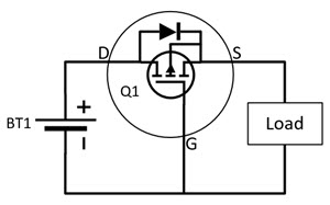
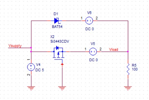
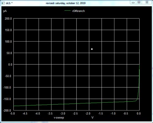
Jon Fuge suggested using a FET for protecting against a battery being installed backwards:

Having read your article on ultra-low power design (an area which interests me greatly); I have another addition which has worked well for me in the past… It uses a P-MOS MOSFET transistor which to the casual glance looks like it's fitted the wrong way around.

When the battery is the correct way around:

FET to avoid backwards battery


  • The internal diode of P-MOS MOSFET Q1 is forward biased allowing the Source to reach Battery voltage – 0.3V
  • The Gate – Source Voltage is Battery Voltage – 0.3V, enough to turn Q1 on; Drain to Source is now low impedance and the voltage drop across Q1 is negligible.

When the battery is reverse biased:

  • The internal diode does not conduct; Source remains at ~0V
  • Gate – Source Voltage never reaches a level to turn Q1 on.

Beware not to exceed the Gate-Source voltage of Q1; if necessary, add a resistor and Zener protection to protect the G-S voltage from being exceeded.

Bing Huang sent a reference to a very interesting patent for a socket that allows an AA or AAA to be inserted in either direction, yet still power a system:

The better coin cell socket in your report on Ultra-Low Power Design reminded me of another battery holder design that works with battery inserted either ways. It is a purely mechanical design but is elegant. However, it is only for AA, AAA, etc type of batteries and not coin cell. It was developed by Microsoft. You can check out the design here:

https://patentimages.storage.googleapis.com/ec/bb/14/2fc3581f86f926/CA2649923A1.pdf

There are other designs in the past, but this seems to be the simplest.

Frequent correspondent Clyde Shappee had some good data:

I read with interest the remarks about reverse battery protection.

I too have used the P-Channel MOSFET solution and it works well.

FET reverse battery protection circuit

D1 is the diode I used for the body diode current measurement.  In simulation as the voltage came up, about 8 mA of current flowed through it before the MOSFET turned on.  V6, 0 V is for measuring the current through the diode.  Likewise, V5 measures current to the load.

Today I simulated it, and with the battery in reverse, the current is quite reasonable, less than 150 pA.

FET reverse battery protection simulation

The voltage drop across the MOSFET was just 2.3 millivolts.   Because I was curious, I checked the current through the body diode and it was on the order of 60 pA.  

This does seem like the ideal solution.

Clyde also mentioned an insidious sneak circuit he found in an MCU. If the batteries in a system were inserted backwards, some 4A were drawn through ESD protection diodes in the MCU's ADC input!

Encoders

I've been getting a lot of inquiries about using shaft encoders lately. Here's an overview, which is probably not complete as there are so many products available today.

An encoder gives position information about a rotating mechanical shaft. An example is a volume control on a radio. In the old days we used potentiometers - variable resistors - to set the gain of the amplifier. Today it's more likely an encoder would translate the position of the shaft (the volume knob) into something an MCU can understand. With a pot there's a mechanical stop at the low and high ends of travel. If there's no stop, an encoder is likely used.

Encoders come in many flavors:

  • Mechanical units have one or more wipers that ride on a circuit board. Those wipers could, for example, generate a binary code representing position.
  • Optical versions beam light through a disk which is scribed. For instance, the disk could have 1000 scribes, so the device will output 1000 pulses per revolution (PPR).
  • Magnetic encoders use Hall-effect sensors.

Their outputs are equally diverse:

  • Incremental encoders just send a pulse stream. Each pulse denotes some amount of angular rotation.
  • Binary and Gray code versions send absolute position information.
  • Quadrature encoders provide two signals each 90 degrees out of phase with each other. While an incremental encoder can't tell you which way the shaft is rotating, quadrature versions do.
  • Fancy units: Many encoders will provide position information via I2C, SPI, or other formats.
  • The rest: Voltage, commutation and many other versions abound.

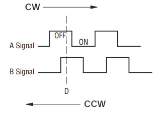
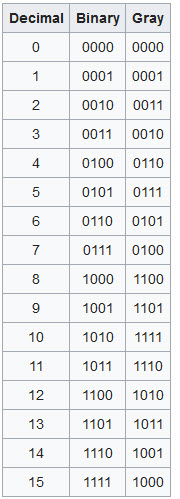
Incremental and quadrature encoders have one innate flaw: You can't translate the outputs to an absolute position. So some of these also sport an "index" pulse, which is a separate signal that is asserted once per revolution. Typically, in manufacturing a technician rotates the encoder to generate the index pulse at some pre-determined position. From that it's possible to figure absolute position (e.g., with an incremental encoder that generates 1000 PPR, if 500 pulses have been detected after the index signal, then the shaft is 180 degrees from the calibrated index position).

Pulses per revolution vary from just a few to 65,536. (That puppy will set you back over $1000, and outputs 16 bits of Gray code).

The cheapest encoders are a half-buck or so in singles and are generally quadrature versions. These offer a dozen or two PPR and are often found as controls, like for the volume control on a radio.  Others are more capable; Digikey lists one QE with 6000 PPR for only (!) $3700.

What does a quadrature encoder's output look like? Here's an example:

quadrature encoder output

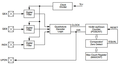
Instead of going into some depth about using a quadrature encoder, check out this excellent reference which includes sample code.

Some MCUs have peripherals that handle quadrature encoders directly. For instance, Microchip offers their Quadrature Encoder Interface, which looks like:

The digital filters remove glitches from mechanical encoders. Microchip has a good reference about this peripheral here.

It is possible to have custom encoders made. In one case we had data coming in spaced at sin2 of the shaft angle. One could use a very high-resolution encoder and interpolate, but the interrupt rate would be astronomical. Instead, we had an encoder made which gave us pulses spaced at sin2 intervals.

Aside - On Gray Code

Gray code is a code developed to eliminate the glitching one can expect from mechanical contacts. With binary many bits change at a time and wiping contacts and create erroneous apparent binary codes. With Gray, only a single bit changes at each count. Here's and example from the Wikipedia page:

Gray code table


Another aside - Servicing Encoder Interrupts

Back in the early 1970s we designed an instrument which used an optical encoder that provided 1000 pulses/revolution.  It was connected to a spinning set of optical interference filters. As one tilts an interference filter, the filter's passband changes, so by measuring the shaft position we could infer the frequency of light passed.

As I recall We had a new sample every 100 us. The processor was Intel's first 8-bitter, an 8008 operating at a blistering 0.8 MHz. With 5 to 11 T-states per instruction only a few could execute between encoder pulses. How to handle that data?

The 8008's interrupt structure was odd, to say the least. It's response to an interrupt was a nearly-normal fetch cycle, except that an interrupt acknowledge signal was generated. External hardware had to supply an instruction on the bus during this INTA. Normally one would jam a one-byte call to invoke one of eight handlers, but that was far too slow for this application. Instead, we had the processor execute a halt instruction located at the beginning of the handler after processing each interrupt. The hardware jammed a NOP, the fastest instruction, in response to an interrupt. That simply resumed execution at the beginning of the interrupt service routine.

Jobs!

Let me know if you’re hiring embedded engineers. No recruiters please, and I reserve the right to edit ads to fit the format and intent of this newsletter. Please keep it to 100 words. There is no charge for a job ad.


Joke For The Week

These jokes are archived here.

Machines don't save you from doing more labor, they just save your employers from paying for more labor.

About The Embedded Muse

The Embedded Muse is Jack Ganssle's newsletter. Send complaints, comments, and contributions to me at jack@ganssle.com.

The Embedded Muse is supported by The Ganssle Group, whose mission is to help embedded folks get better products to market faster.