|
||||||||||
You may redistribute this newsletter for non-commercial purposes. For commercial use contact jack@ganssle.com. To subscribe or unsubscribe go here or drop Jack an email. |
||||||||||
| Contents | ||||||||||
| Editor's Notes | ||||||||||
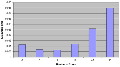
Did you know that for many reasonably-parallel applications multicore starts to degrade performance once more than around 8 cores are used?
Engineering without metrics isn't engineering. That's art. Engineers measure things and use the numbers to guide their work. That's what my Better Firmware Faster seminar is all about. This one-day event shows quantitatively how to improve your firmware processes. Find out how you can bring this class to your facility, to help your engineers achieve world-class code on a shorter schedule. More info is here.
On June 27-28 NIST will host the Sound Static Analysis for Security Workshop at NIST's facility in Gaithersburg, MD. To quote from their communications "this two-day workshop is focused on decreasing software security vulnerabilities by orders of magnitude, using the strong guarantees that only sound static analysis can provide. The workshop is aimed at developers, managers and evaluators of security-critical projects, as well as researchers in cybersecurity." I plan to attend. It's free, and there's more info here. |
||||||||||
| Quotes and Thoughts | ||||||||||
"I love fools' experiments. I am always making them." Charles Darwin. |
||||||||||
| Tools and Tips | ||||||||||
Please submit clever ideas or thoughts about tools, techniques and resources you love or hate. Here are the tool reviews submitted in the past. One way to extract debugging info from an embedded system is send it out over a serial interface, such as I2C. Most digital scopes can decode these interfaces, so you can watch the data in real time. Don't have a serial interface? If you've got two GPIO bits, then you do. This video explains how. This month marks the 100th anniversary of the invention of the flip flop. Now, that was long before transistors... and not long after tubes were invented. More here. |
||||||||||
| Freebies and Discounts | ||||||||||
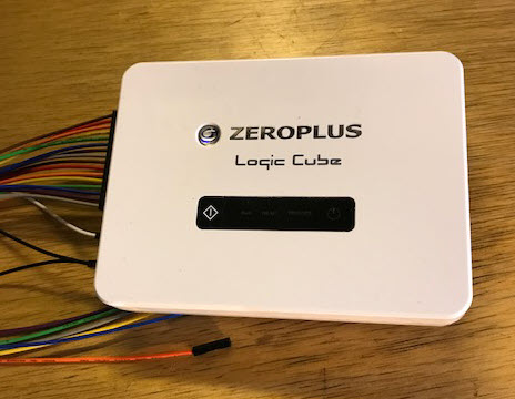
This month we're giving away the Zeroplus Logic Cube logic analyzer that I review later in this issue. This is a top-of-the line model that goes for $2149.
Enter via this link. |
||||||||||
| Power Evolution | ||||||||||
If you've raised teenagers you've probably been frustrated when the young folks seem unable to learn from anyone's experiences other than their own. Each generation seems to repeat the same mistakes. That's the reason I often write about embedded disasters; we engineers had better learn from the failures of others, so we don't get caught in the same trap. But it's wise to sometimes reflect on what has gone right in this industry. One of those areas is that of power management. Not infrequently the This Week's Cool Product section of the Muse is some sort of power management IC. If you haven't followed modern power handling, prepare to be astonished. Did you know the SoC in a mobile phone has multiple voltages, and those values are changing constantly in response to SoC demands? A sudden need for major computation will cause the power-management chip to scale the voltages up; when there's less to do they ramp down to save the battery. Some of these SoCs have proprietary schemes to reduce the applied voltage to just above the point where the transistors become unreliable. Multiple power domains allow parts of the SoC to shut down when not needed. Or did you know a modern high-end CPU, like the one in a PC, can take over 100 amps? That's incredible for a square centimeter of silicon. Sometimes there are nearly a thousand "pins" just dedicated to power and ground. At the other end of the spectrum some MCUs can run for years from a coin cell, though getting this to work is much harder than it appears. I was reflecting on this when a press release for Analog Devices' LTM4661 came in. It's a new voltage regulator that can supply 4 amps. The entire thing, other than some external capacitors, is in a 6.25 x 6.25 mm package. I often show visitors their ADP172 which is a linear regulator that is in a 1 x 1 mm package - so small it's hard to see. In the olden days all we had were linear supplies. Where I worked we had custom-made transformers to reduce the mains to lower voltages which were rectified and filtered. The filter capacitors were big beasts about the size of a drinking glass. The filtered voltage went through one or more paralleled power transistors to the circuit boards. The transistor's base controlled the voltage coming out of the transistor; the base itself was driven by a circuit that adjusted the base voltage to get the required 5 volts (or whatever was needed).
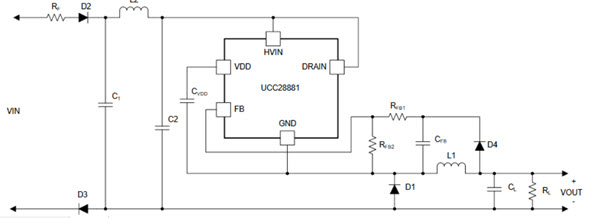
A simple linear power supply If one wanted regulated 5 volts from the supply, it was common to pick a transformer that output around 12 volts. The excess was to account for diode and transistor drops, as well as variations in the AC input. If 12 volts went into the transistors and 5 was wanted to the circuit, say at 10 amps, that meant 70 watts was converted to heat in the transistors. Wasted. The transistors could burn up, so they were bolted to large heat sinks, often with a fan. The power supplies were often larger than the logic boards. Linear regulators are simple and reliable, but very inefficient. A solution, the switching regulator, came into being in the 70s. The idea is that the series pass transistor is always either completely on or completely off. An inductor and capacitor convert this pulsing waveform into a nice steady DC level. The circuit needed to control the pass transistor is somewhat complex. Since the transistor is either on or off (that is, not in a partially conducting state) little heat is generated and the regulator is very efficient. You'd think that with all of the switching going on the DC voltage would have a lot of ripple, but that's not the case. The previously-mentioned LTM4661 has only about 3 mV. Efficient use of power is desirable, but in some applications is critical. Companies that build very large uninterruptable power supplies that run entire data centers will do almost anything to get even a fraction of one percent increase in efficiency. These units provide thousands of amps; every extra wasted watt goes into the air, which means more powerful air conditioners are needed. Those, too, sometimes run from the UPS, resulting in even more heating and yet a need for a bigger A/C, in a vicious circle. A variation is the off-line switcher, which dispenses with the transformer. That saves a lot of weight, form factor and money. They are a bit scary, as the mains (110 VAC here in the USA) goes right into the circuit without having been stepped down. These are common today. Here's an offline switcher using TI's ucc28881; this part can accept a terrifying 700 AC volts as input:
The ucc28881 is under $2 in singles. Parts like it have made designing these sorts of power supplies easy. And they are reliable. But it wasn't always so. In the 70s I worked for a company that made all sorts of instrumentation. One unit - which, happily, I wasn't involved with - measured fat and protein in ground meat using optical techniques. For some reason the lead engineer convinced management that it needed an offline switcher, which he was happy to design. How hard could it be? None of these nifty ICs were available, so he designed a power supply using discrete components. It was complex. It kept failing, always spectacularly. After all, a wall outlet provides a lot of energy. The one-month design cycle stretched to over a year. The machine eventually went into production and thousands were shipped. Every time there was a thunderstorm in the Midwest, hundreds of units blew up. The extra energy lightning coupled into the AC mains was more than the design could withstand. That product nearly bankrupted the company. We've come a long way, in all aspects of electronics design. |
||||||||||
| Tin Whiskers and Cupolas | ||||||||||
Duane Mattern responded to last issue's comments about tin whiskers. His TV failed. Suspecting a whisker problem, he put the main board in the oven at 385° for ten minutes to reflow the solder... which fixed the problem! Here's his technique. Last year our TV died. Not being clever enough to try baking boards, I simply replaced the entire unit. But I usually dismantle failed products to see how they work and what tech is inside. The electronics was interesting, but, better, there were two huge sheets of plastic. Figuring they might be good for something, someday, I saved them. Last summer we finished building a barn, but it really needed a cupola. That plastic was the perfect substrate for the curved pieces under the copper.
|
||||||||||
| Review of the Zeroplus LAP-C Logic Analyzer | ||||||||||
Last October I reviewed Zeroplus's LAP-F1 logic analyzer. That is a high-end product that offers pretty much any feature you could ask for. The company also sent me one of their more affordable units, the LAP-C, AKA the Logic Cube. The LAP-C comes in a number of flavors with prices from $139 for 16 channels and 32k bits of memory per channel, up to $2,149 for a unit with 32 channels and 2 mb/channel. I evaluated the most expensive and capable unit in the lineup. The software UI is Windows-only, and Windows 7 is recommended. The manual states that "uncertified workaround exists" for Windows 8.1 and 10; I used the latter and had no problems. Various on-line reviewers cite installation difficulties, but the software installed painlessly for me. First, the specs:
The unit is small and is in a nice-looking plastic box. There's not much to the hardware; a LED lights up when it's powered and a single button can command captures. Another LED illuminates when it is acquiring data, another when the data is being sent to the PC, and yet one more lights when a trigger event occurs. It came with a complete set of cables and hookup clips. The user interface is a little intimidating at first. Pretty much everything can be controlled from the quick-access toolbar. The waveform display shows fairly tiny signals, at least to my old eyes. I wished I could make them bigger in the vertical dimension. Turns out, they can be any size you'd like. In fact, the font size selector is right there on the quick-access toolbar. Just about everything on the screen can be configured: font size, colors, shortcut keys, tool bars, etc.
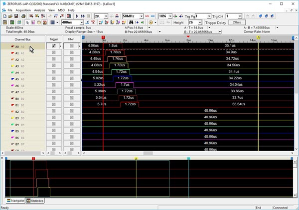
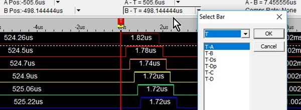
The user interface. Note all of controls on the quick-access toolbar. Below that, a strip reads out cursor information. Below that is the waveform display, which is a zoomed in portion of the data. The bottom windows is the complete set of data. To the left are the signal names, followed by trigger and filter controls. Navigation is very fast as are screen updates. Even when acquiring 2 million bits for each of the 32 channels, the upload to the PC took only 5 seconds. Drop that to 256 kb/channel and the upload is under a second. The mouse scroll wheel pans the waveforms left and right. In the picture above the red cursor (vertical line) is the trigger. A and B cursors are enabled for measuring signals, and you can add up to 250 more. Above the waveform display a strip shows the positions and deltas of three cursors. The next picture shows this, and a drop-down menu that lets you select which cursors (I've added a few) are shown in that strip.
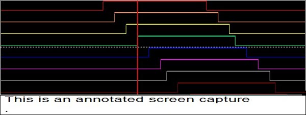
Cursor selection The UI has a built-in screen capture which I thought was a little silly as we all have such tools. Except you can add an annotation, which is pretty sweet if you're saving a lot of screen shots and need to know what each one consists of.
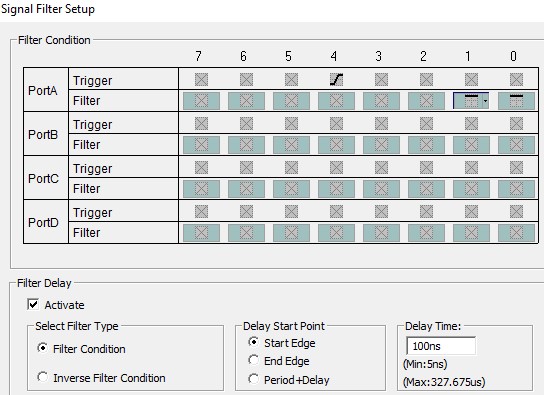
Screen shot with annotation You do have to re-specify if you want a complete screen (you won't - it's the entire desktop) or a region, and if you don't want to save it to a file, instead putting it on the clipboard. I wish it had remembered my prior selection. Or, you can export the data to a text or .CSV file. If the former, the file contains all the analyzer's setup information. There are a lot of options to limit the data - for instance, it can export only changes in data, or particular busses. With logic analyzers it's all about the memory. The LAP-C is nice in that it can filter signals to use less of that resource. That is, samples are stored only when certain user-defined signals are high or low. And, one can add a delay so signals are filtered for a period after the filter condition is satisfied.
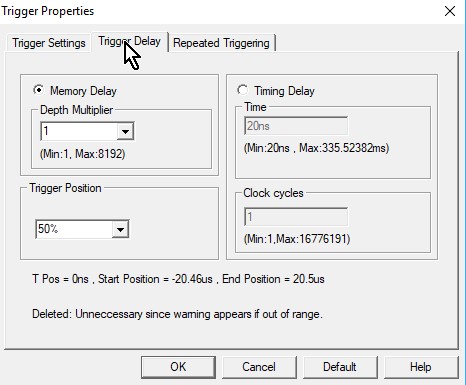
Signal filters Compression is another memory-saving feature. When enabled it will compress the data, in real-time, by a factor of up to 256, depending on how fast the signals change. It's off by default as rapidly-changing signals could net a negative compression ratio. For units with 32 channels, a "double mode" is available when sampling 16 or fewer inputs. This mode uses the memory normally dedicated to the 16 unused channels to double the acquisition memory. Triggering is not terribly sophisticated (for incredible triggering see the LAP-F1 model I mentioned earlier). It will trigger on edges and levels, and pattern-trigger on as many channels as you'd like. Triggers are easy to set up. In the first screen shot above, next to each signal name there's a box. Click on it to cycle through triggering modes. A trigger delay causes the LAP-C to store data a certain time after the trigger event occurs. If, as in the following picture, the "Memory Delay" is selected, the unit starts acquiring data after a multiplier of the memory depth has happened. So if the memory depth is set to 32 kb, and the multiplier to 10, then the analyzer starts to store samples after 320 kb of data has happened. I'm not entirely sure what the value of this feature is. However, one can also set a delay based on time: delay acquisition until so many ns after the trigger, or so many clock cycles have occurred.
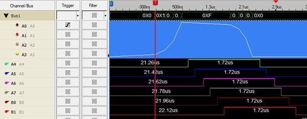
Trigger delay Like a lot of these USB logic analyzers there's no way to trigger on pulse widths. But a $100 optional (included on the highest-end unit) add-on will enable triggers on times between edges, or triggers on a specified duration of a signal. Some of the USB analyzers will only do a single-shot acquisition. The LAP-C allows repeated acquisitions; after filling the memory and displaying the results it reacquires another memory-load, repeating till you hit the stop button. An output goes high when the unit is sucking in data. Connecting that to a scope, I found that with the shortest buffer (2 kb) it reacquires every 500 ms, rising to 1.6 s for a 512 kb buffer, and to 5 s for 2 mb. This was with a 50 MHz acquisition rate so the actual reading of data from the target board was a tiny percentage of these numbers. I don't like that you can't scroll left and right through the waveform when the unit is repeatedly acquiring. A nifty feature is the ability to show busses as analog data. Suppose you're monitoring the inputs to a DAC. Tell the LAP-C to group those into a bus, and then display both the digital signals and an equivalent analog representation, like this:
Note signals A0 to A3 are grouped into a bus. The numeric bus value is in the top line, below that (in blue) is the equivalent value as an analog waveform. Another intriguing feature is the ability to filter noise and other gunk from the display. For instance, a bus that is transitioning may be in some uninteresting and distracting state. You can tell the LAP-C to ignore transitions that are shorter than some period. The range for the filter is 20 ns to 1.3 ms. In the state mode another filter can eliminate signals that are shorter than some number of clocks; the allowed range goes from one to 200 clocks. As with most logic analyzers the user can specify the numeric base for displayed data. Generally analyzers support decimal, binary, and hex. The LAP-C handles those, but adds ASCII and, of all things, Gray code. I don't run into the latter much anymore, but occasionally it is useful. Some encoders output Gray. With Gray code only a single bit changes at a time. The code is useful in, among other things, electromechanical systems where not all contacts will change at exactly the same time; with a binary code this can lead to momentary incorrect counts.
When counting in Gray Code only one bit changes at a time My overall impression of the LAP-C is very positive. The UI is fast and responsive, and reasonably intuitive, though I did read through the entire manual. It makes good use of the function keys. And, for the fashion-conscious, it comes with a very nice hard zip-up carrying case which could be the ultimate in nerd accessorizing. |
||||||||||
| Jobs! | ||||||||||
Let me know if you’re hiring embedded engineers. No recruiters please, and I reserve the right to edit ads to fit the format and intent of this newsletter. Please keep it to 100 words. There is no charge for a job ad. |
||||||||||
| Joke For The Week | ||||||||||
Note: These jokes are archived at www.ganssle.com/jokes.htm. J.G. Harston sent this: I can't claim any credit, but this is currently doing the rounds as the deadline for the new General Data Protection Regulations approaches: Q: Do you know a good GDPR specialist? A: Yes. Q: Can you tell me their email address? A: No. |
||||||||||
| Advertise With Us | ||||||||||
Advertise in The Embedded Muse! Over 27,000 embedded developers get this twice-monthly publication. . |
||||||||||
| About The Embedded Muse | ||||||||||
The Embedded Muse is Jack Ganssle's newsletter. Send complaints, comments, and contributions to me at jack@ganssle.com. The Embedded Muse is supported by The Ganssle Group, whose mission is to help embedded folks get better products to market faster. |