|
|
||||
You may redistribute this newsletter for non-commercial purposes. For commercial use contact jack@ganssle.com. |
||||
| Contents | ||||
| Editor's Notes | ||||
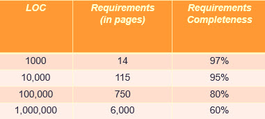
Do you have any sense of your requirements needs and their completeness? The table above (derived from The Economics of Software Quality, by Capers Jones) is his empirical results from thousands of software projects. As engineers we should be guided by hard numbers, both in working out formulas, and in guiding firmware development. My seminar, Better Firmware Faster, is packed full of numbers that should guide our processes, like the cost of firmware, aspects of scheduling, bug rates, and lots more. Sure, software engineering is a very new discipline and we have lots to learn. But there's lots we do know, plenty of data on which processes and approaches work. Are you happy with your team's results? Are you anxious to learn new ways to get better code to market in less time? Bring my one-day class to your facility to learn how to ground your firmware efforts in hard, quantifiable, numbers. A note on phone scammers: My nonogenarian parents were taken for $149 and an infected computer when one of those bogus "I'm from Microsoft and your computer needs work" callers phoned. The very next day I got 5 such calls in one morning. I signed up for Nomorobo, a free service that (at least in the USA) blocks most of these execrable calls. It is working well. Recommended. A year or so ago, when I got one of these calls, I pretended to succumb, listened carefully, and pretended to type in the stuff they wanted me to do. Then I shouted "There's smoke coming from my computer - what should I do." The caller asked me to calm down. "Now there's fire coming out. What should I do? Should I save my children or toss the computer out the window." He instructed me to do the latter. Then, in a pretend panic, I said "I tossed it out, but it's in a pile of leaves and the house is burning down!" After that I was laughing too hard to continue the deception. |
||||
| Quotes and Thoughts | ||||
John Hartman wrote: Your Dijkstra quote about "conceptual hierarchies" reminds me of the adage "there is no problem that can't be solved by another layer of abstraction - except for the problem of too many layers of abstraction." https://en.wikipedia.org/wiki/Fundamental_theorem_of_software_engineering |
||||
| Tools and Tips | ||||
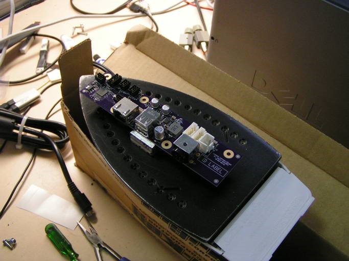
Please submit clever ideas or thoughts about tools, techniques and resources you love or hate. Here are the tool reviews submitted in the past. Tom Lock had a cool (hot) suggestion:
|
||||
| Freebies and Discounts | ||||
Win an ee701 differential preamp for a scope! Thanks to ee-quipment for donating the unit. A review is later in this issue. One lucky Muse reader will win this at the end of November, 2017.
Enter via this link. |
||||
| More on Faults, Errors and Failures | ||||
In Muse 336 I ruminated on how poorly fault, error and failure are defined. Dev Banerjee disagreed:
Tom Harris sent this: |
||||
| Automatic Testing | ||||
Steve Johnson had a story about building automatic tests:
He later added:
|
||||
| Is A Datasheet a Guarantee? | ||||
What is a vendor's responsibility to provide components that live up to the datasheet? Conversely, how should the datasheet live up to the component? I've gotten several emails recently from engineers who have discovered that various parts just do not work as advertised. This is hardly a new phenomena; I can remember in the 1970s when NEC came out with their first floppy disk controller. The datasheet was dead wrong on several registers. It's an old joke, or rather howl of despair, that so often register bits are documented inverted or transposed. Anyone who has worked in this industry for more than a short while has been burned by these problems. In the olden days parts were simple and datasheets short. It wasn't hard to fully charaterize a component. Today, even the venerable 7404 hex inverter has a 27 page datasheet! MCUs and SoCs are much more complex. A little 8-bit device can have a datasheet hundreds of pages long; those for more sophisticated devices can occupy thousands of pages. Humans are not perfect, so how can one expect perfection in the documentation? Yet, it used to be that the datasheet was a guarantee. If you used the part as documented, the company would stand behind its functionality. Datasheets are routinely incorrect. The parts themselves often have flaws; one correspondent complained that in a common 8 bit MCU one (out of a few dozen) of the instructions doesn't work correctly. The vendor's defense is that "no one uses assembly anymore, and C compilers don't emit this instruction." If a datasheet is not a guarantee, what is? Customers who discover faults can report them to the vendor, who (we'd hope) would either correct the part/documentation, or issue an errata sheet. But another common complaint is that at least some vendors never respond to requests for help. Today we're often vectored to a support forum, where much of the "support" comes from well-meaning customers. These folks may not have the company's ear. The forums are more efficient for the vendor, but often fail to satisfy customer needs. If I specify a 7404, whose datasheet claims the max tPLH is 22 ns, then I can surely expect the part, if used correctly, will never be slower than that. Shouldn't we be just as sure about the behavior of, say, every mode of an MCU's timers? What's your take on this? And I'd love to hear from vendors, anonymously or otherwise. |
||||
| Review of a Differential Preamp | ||||
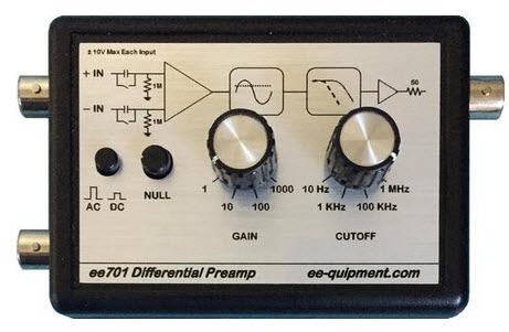
Need more gain for your scope? The ee701 differential preamp from ee-quipment might be just the ticket. As the name suggests, it's a two-input differencing amplifier that lets you probe signals from microvolts to volts. The specs are:
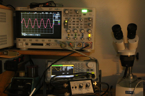
The ee701 differential preamp. Picture swiped from vendor's web site. The picture speaks for itself - you can see the input can be DC or AC coupled, and the gain and cutoff frequency are easily selectable. The two BNCs to the left are the signal inputs and the one on the right goes to the scope. What's not shown is the wall-wart which plugs in on the right side. I ran one through its paces and it behaves just as advertised. In the photo below you can see it connected to my Siglent SDG 2042X dual-channel arbitrary waveform generator. In this case the two channels drive the ee701's inputs. I've set the ARB to generate two synchronized sine waves of the same frequency. One channel is putting out 4V peak-to-peak; the other 4.010 volts. With the preamp's gain set to 1000 that 10 mV difference is huge on the scope.
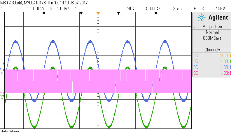
I can think of two uses for this unit. The first is to amplify very low-voltage signals. My Agilent scope's most sensitive scale is 1 mV/division, which isn't adequate for microvolt levels. The second is working with signals that have a big common mode component, as shown above. I tried the same experiment without the preamp, feeding the two signals into two scope channels, and then invoking the subtraction feature in the math menu to effectively simulate the preamp's operation. The resulting signal was incomprehensible - it's shown in pink here, with a scale of 50 mV/division:
Further experimentation showed that cranking up the scope gain on the two input channels reduced the size of the "noise," though at no gain could I make out the 10 mV difference. The frequency of this this signal matches the 4 GS/s scope sampling rate. This correlates fairly well with quantization error of the scope's 8 bit A/Ds. As a sanity test I set one of the ARB's channels to 4 V and the other to 5V, and the subtraction worked as expected. I found the same effect on an another scope from a different vendor. It's a nice unit, and recommended if you need to handle small signals, or signals with a large common-mode component. The only thing I didn't like about it is that there is no LED indicating that it's powered on, which is a pretty minor quibble. This preamp is pretty similar to Tektronix's ADA400A, though at $395 sure beats Tek's $2000 price. I did a video review here. |
||||
| Jobs! | ||||
Let me know if you’re hiring embedded engineers. No recruiters please, and I reserve the right to edit ads to fit the format and intent of this newsletter. Please keep it to 100 words. There is no charge for a job ad. |
||||
| Joke For The Week | ||||
Note: These jokes are archived at www.ganssle.com/jokes.htm. When talking about firmware standards I often point to stop signs - even when viewing the sign from the back, we know what it is as the shape is standardized. So sometimes I take pictures of unusual signs, like this one in New Orleans:
|
||||
| Advertise With Us | ||||
Advertise in The Embedded Muse! Over 27,000 embedded developers get this twice-monthly publication. . |
||||
| About The Embedded Muse | ||||
The Embedded Muse is Jack Ganssle's newsletter. Send complaints, comments, and contributions to me at jack@ganssle.com. The Embedded Muse is supported by The Ganssle Group, whose mission is to help embedded folks get better products to market faster. |