|
|
||||
You may redistribute this newsletter for non-commercial purposes. For commercial use contact jack@ganssle.com. |
||||
| Contents | ||||
| Editor's Notes | ||||
As engineers we should be guided by hard numbers, both in working out formulas, and in guiding firmware development. My seminar, Better Firmware Faster, is packed full of numbers that should guide our processes, like the cost of firmware, aspects of scheduling, bug rates, and lots more. Sure, software engineering is a very new discipline and we have lots to learn. But there's lots we do know, plenty of data on which processes and approaches work. Are you happy with your team's results? Are you anxious to learn new ways to get better code to market in less time? Bring my one-day class to your facility to learn how to ground your firmware efforts in hard, quantifiable, numbers. |
||||
| Quotes and Thoughts | ||||
From a bit to a few hundred megabytes, from a microsecond to a half an hour of computing confronts us with completely baffling ratio of 109! The programmer is in the unique position that his is the only discipline and profession in which such a gigantic ratio, which totally baffles our imagination, has to be bridged by a single technology. He has to be able to think in terms of conceptual hierarchies that are much deeper than a single mind ever needed to face before. - E. W. Dijkstra |
||||
| Tools and Tips | ||||
Please submit clever ideas or thoughts about tools, techniques and resources you love or hate. Here are the tool reviews submitted in the past. Mark Dalphin responded to my call for a fast file content-indexing/search tool:
Martin Honeywill wrote:
|
||||
| Freebies and Discounts | ||||
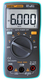
Win an Aneg AN8001 true-RMS 6000 count digital multimeter. It's not particularly fancy, but the price is right for one lucky Muse reader.
Enter via this link. |
||||
| An Alternative User Interface | ||||
When I was 11 or 12 I made spending money mowing lawns for the neighbors. The price was $1.50 as I wasn't smart enough to base it on acreage. I hated every minute of it. Today, I take a certain pleasure in mowing our lawn. The tractor is quite noisy, so I wear hearing protectors that have an FM radio. Car Talk zaniness or Pandora streaming Michelle Shocked makes the chore a delight. Alas, the yard is rather bumpy; a beer in the cup holder spills (at least it waters the lawn). And my woodworking machines are quite loud so I have to use the hearing protectors when using them, too. My Worktunes protectors had a nice LCD panel that showed the frequency of the FM station. After many years of service they recently failed. The replacement has all the same features, but without the display. Instead, a computer-generated voice gives the frequency when they are first turned on, and when tuning to a new station. One button has two functions, selected by pressing it once or twice. After such selection the voice speaks the name of the mode. It's an interesting way to save a buck or two. Speakers already exist, and it's easy to generate a voice with a small microcontroller. The product is probably a bit more reliable absent the cabling and possibly an LCD connector. |
||||
| Zeroplus LAP-F1 Logic Analyzer | ||||
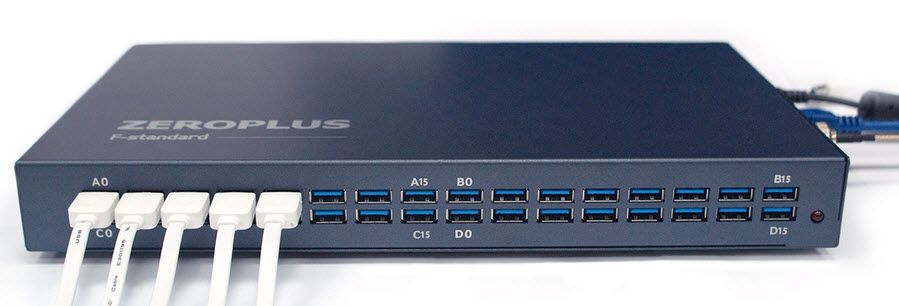
Zeroplus, a Taiwanese provider of Logic Analyzers (which I abbreviate as LA) and similar tools, sent me their flagship LAP-F1-64 LA for review. They also sent one of their much-less expensive LAP-C Logic Cubes which I'll review in a later Muse. The LAP-F1 comes in a variety of models with different memory depths and numbers of channels, and with different optional probes. This is a high-end, full featured unit which carries a correspondingly heavy price tag. Here's a short summary of the features:
The unit is in a heavy-duty aluminum box. It connects to a PC over USB 3.0.
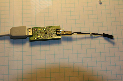
It comes with a 156 page manual which is barely able to cover the huge wealth of features. A lot of instruments from the East have English manuals that are sub-par; the LAP-F1's is not bad. Occasionally the English is fractured and, more rarely, a feature's description borders on incomprehensible. It came with a cornucopia of probes. The low-speed (120 MHz) probes handles two signals each. The also-provided faster (200 MHz) probes that take one signal each. But these are not the simple wires you'll get with most LAs. The end of each of these 30 cm white cables goes into a PCB; from there 50 mm leads go to the unit under test. The PCB is shrink-wrapped to protect it, but I cut one open and found that each signal is routed through a number of resistors and capacitors, plus an IC, presumably forming an impedance-matching network. Given the unit's ability to sample really fast signals, this is a big improvement over "probes" that are just wires. (For more on probes in general, see this.)
Probe PCB with the insulating heat shrink tubing removed. The white cable to the left goes to the LA; the wires to the right to the target system. Only one signal is attached, but this probe can handle two. Note the "4" - each signal is numbered. With 64 channels color-coding wouldn't work too well. Update: Turns out a variety of cable lengths are available - up to 250 cm! Few logic analyzers can support such a long cable, but the LAP-F1 can because of the impedance-matching network in the picture above. The application appears to get updated fairly often. I didn't like it that if an update is needed, when you start the application it appears to hang. Turns out the updater is in control, but winds up hidden behind other windows you may have open. And the download (a quarter gigabyte .zip file), presumably from a server in Taiwan, is moderately slow. The unit is powered by a wall wart, and there's no power switch. A while back I put a power strip on my bench within easy reach; each outlet has its own switch, so this was no impediment for me. Signal threshold voltage is programmable. Each of the 4 ports (16 signals/port) can have a separate level, adjustable with an astonishing 10 mV resolution. Everything in the GUI is configurable, such as window colors (I didn't care for some of the defaults so changed those), hotkeys, toolbars, etc.
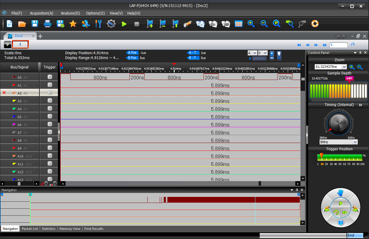
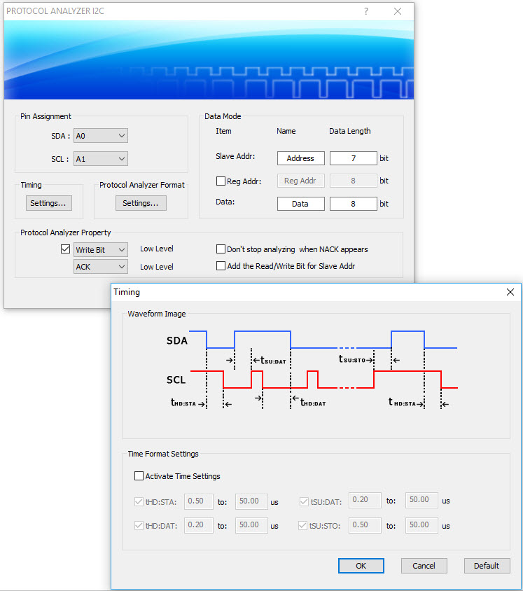
General screen layout. The bottom window is a god's-eye view of the entire set of captured data. The circular control on the bottom right provides quick access to a number of commonly-used functions; I preferred using the menus. Above it is the trigger position, above that is the acquisition rate knob, for when using the internal clock. The desired number of sample is above that. Normally, an application's Save As function is boring and predictable. With the LAP-F1, though, the Save As and Export features have endless options. You can select how the exported data is formatted, which channels to export (by many different parameters), all or only changed data, ranges of data exported, details of decoded protocols, and more. I have never seen so many options available. I use a utility called SnagIt to capture screen shots; the LAP-F1 application has a built-in screen capture that will snag any portion of the entire desktop, though I suspect most people will only save a portion of the logic analyzers screen. Like most LAs, one can add or delete channels and busses to the display. What is somewhat unique, though, is that when adding a bus one can select another input signal to be a chip select, and specify which, or both, edge to activate on. The bus signals are latched when the chip select meets the activation condition. Sure, one could set a trigger to do this, but by using a separate chip selects one could latch multiple busses using different activation conditions. The LA includes protocol converters, of course. Most do, even inexpensive models. But... I have never seen so many converters and don't even know what most of them are. The manual claims over 120 included. There are 14 just for digital audio. Eleven for memory interfaces. Half a dozen for power management. And many have lots of options. Here's an example for I2C:
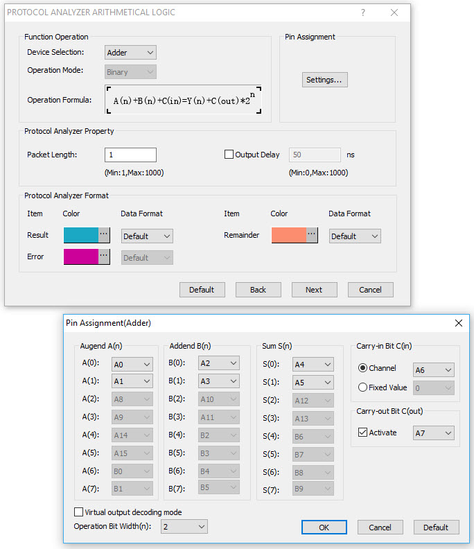
Some of the "protocols" are quite unique. Under the general rubric "Basic Logic Application" you can combine LA inputs into logic "circuits." For example, a "protocol" could be inputs driving a JK flip flop. Or a binary adder, multiplier, or any of a number of other virtual components. Here are the setup windows for an adder:
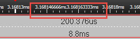
That's pretty cool. I did find that sometimes the times were displayed with an inappropriate number of digits, to the point where one number runs into the next. No doubt that will get fixed in a future software release:
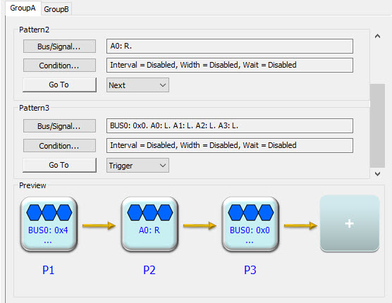
The LA supports the usual triggering modes, plus some that are rarely, if ever, found on other logic analyzers. One that was interesting was a trigger that is armed after a pattern on the inputs is detected, but that triggers only after that detection plus a settable amount of time goes by. Another arms the trigger when, for example, a signal's rising edge is detected, but the trigger only takes place if a certain pulse width (min or max) is exceeded. All LAs allow one to set a pattern to specify the trigger condition. Some allow multiple patterns which must occur in some order. The LAP-F1 supports multiple patterns, and it nicely draws a diagram as you add new trigger conditions:
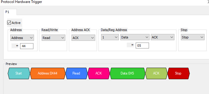
Here's the interesting thing: The LAP-F1 supports a ton of sequential conditions, each of which must be satisfied before the trigger occurs. How many? I got tired of adding conditions after 50. The manual indicates the unit can handle 256 conditions. That's an incredible capability. Six of the supplied protocols can cause a trigger (I2C, I2S, SPI, SVID, UART, CAN2.0B). The trigger setup screens build a picture of the triggering condition as you enter information. In the following picture, see how the Preview shows an address of 0x44, as I entered in the dialog box, and data of 0x5:
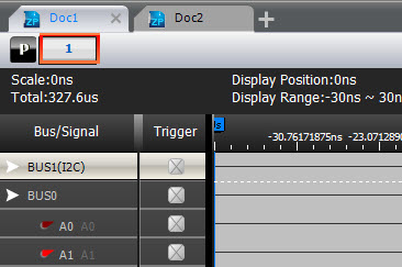
Like web browsers, the LAP-F1's application has tabs for multiple windows. Click on the "+" button and another tab is added:
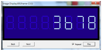
The tabbed windows are called "files", and each "file" displays the acquired data. So, you could acquire a set of data, and then go to another "file" and get more data. The usual window arrangement tools are there to allow one to look at "files" in isolation or tiled vertically or horizontally. A nice feature is that each "file" can have its own LA setup parameters. File A may have one set of triggers, and maybe signals arranged as busses, while file B uses different triggers and signal displays. Switching between files reconfigures the LA. And, uniquely, the there is a "file" comparison feature that shows the diffs between acquired signals. Working with a display? The LAP-F1 will show the digital data sent to the display graphically (for ten different display protocols). I didn't try this feature, but this is a picture from the user manual:
Just as a scope can mathematically combine two signals, the LAP-F1 can combine acquired signals or busses by adding, subtracting, multiplying or dividing them. Or, one can combine them using Boolean operators. If the LAP's memory depth isn't sufficient, there's an optional Long Time Record function that shoots the data into your PC's disk. The manual warns that a pretty decent PC is needed. It appears to me that there are limits to this; you probably can't record all 64 channels at a 200 MHz rate for long. But this is a useful feature for hunting really elusive bugs. Searching in the disk-based data is supported. In the interest of brevity I won't go into much about navigating in the acquired data. Suffice to say that all of the usual nav tools are there, including some less common, like detailed (and very customizable) statistics about the data. Navigation is fast and intuitive. Sophisticated searching is supported. The UI is pretty intuitive, but I had to refer to the manual from time to time. Partly this is because there are so many features available, and partly it's because one menu screen will seem incomplete until a selection is made, and then another screen appears with more options. I got used to the UI quickly but, unusually for me, read the entire manual while playing with the features. The logic analyzer and the Windows application are very fast. The more complex the signals, the longer the upload, so the unit is clearly compressing the data. I suspect that with 64 channels monitoring complex signals you'd have to wait at least a number of seconds for an upload, but didn't test this. The last few years have seen an explosion of very inexpensive logic analyzers, many in the few-hundred dollar range. The LAP-F1 is not one of these; this is an instrument with every possible feature. The price ranges from $2500 to $5500 depending on the memory depth and number of channels. The option Long Time Record feature bumps that up by $2000. This is an extremely versatile logic analyzer which has a ton of useful features, some of which I have not seen on any other instrument. Impressive. |
||||
| On Faults and Failures | ||||
In the last Muse I noted that we don't have generally shared definitions of such basic terms as fault, failure, and error. That sparked some dialog with readers. Phil Koopman wrote:
Harold Kraus had some worthwhile background info and comments:
|
||||
| Laser Printer Optics | ||||
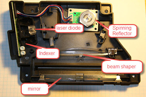
When something electronical fails around here I'll often disassemble it to try and learn something about how it works. One of our laser printers bit the dust recently. The optical path is pretty intriguing. Here's a picture of the optics:
A laser diode shoots a beam to the spinning reflector. Each of the reflector's six sides are highly polished. It spins in a complete circle. This is a rather ingenious design; if a simple mirror were spinning most of the time the beam would be directed in useless directions. The hexagon shape means the beam is usually aimed generally towards the optics that passes it to the drum.. The reflected beam passes through a clear plastic beam shaper. You can see its convex shape, bulging up towards the reflector. I suspect that the odd shape is to account for the longer path length when the beam is at the far edges, compared to a shorter length when in the middle of the shaper. Then, the beam bounces off a mirror and is directed to the printer's drum (not shown). As the spinning reflector directs the beam to the left, it passes through a lens and then to an "indexer" - a photodiode - on the PCB. That is probably used by the firmware to mark the absolute position of the reflector. The motor appears to be a stepper, so, given an index pulse, the code knows the position of the reflector at all times. Pretty cool. |
||||
| Jobs! | ||||
Let me know if you’re hiring embedded engineers. No recruiters please, and I reserve the right to edit ads to fit the format and intent of this newsletter. Please keep it to 100 words. There is no charge for a job ad. |
||||
| Joke For The Week | ||||
Note: These jokes are archived at www.ganssle.com/jokes.htm. Mike Lillywhite sent this: What is the SCM tool of choice for the Rebel Alliance? Subversion. |
||||
| Advertise With Us | ||||
Advertise in The Embedded Muse! Over 27,000 embedded developers get this twice-monthly publication. . |
||||
| About The Embedded Muse | ||||
The Embedded Muse is Jack Ganssle's newsletter. Send complaints, comments, and contributions to me at jack@ganssle.com. The Embedded Muse is supported by The Ganssle Group, whose mission is to help embedded folks get better products to market faster. |