|
|
||||
You may redistribute this newsletter for non-commercial purposes. For commercial use contact jack@ganssle.com. |
||||
| Contents | ||||
| Editor's Notes | ||||
Did you know it IS possible to create accurate schedules? Or that most projects consume 50% of the development time in debug and test, and that it's not hard to slash that number drastically? Or that we know how to manage the quantitative relationship between complexity and bugs? Learn this and far more at my Better Firmware Faster class, presented at your facility. See https://www.ganssle.com/onsite.htm for more details. Some Apollo core rope memory was found in a trash heap. A clever fellow was able to decode it. And here and here |
||||
| Quotes and Thoughts | ||||
"The ratio of time spent reading versus writing is well over 10 to 1. We are constantly reading old code as part of the effort to write new code. ...[Therefore,] making it easy to read makes it easier to write." - Robert C. Martin |
||||
| Tools and Tips | ||||
Please submit clever ideas or thoughts about tools, techniques and resources you love or hate. Here are the tool reviews submitted in the past. Jakob Engblom writes an interesting blog, and two recent entries give a worthwhile perspective on testing. Part 1 and part 2. |
||||
| Freebies and Discounts | ||||
Win a copy of the book Embedded Software Development for the Internet of Things. The contest runs till the end of March. Enter via this link. |
||||
| A Simple Way to Debug PIC-Based Systems | ||||
Daniel McBreaty has a simple way to debug code in PIC-based systems.
I first wrote a bit-banging UART for an 8085 in the 1970s. It, like the code above, relied on timing defined by loops. I wonder if anyone has done this using an interrupt-based timer? |
||||
| Blame the Tools | ||||
The C language revolutionized embedded development. Before it gained traction in the 1980s, most developers worked in assembly language. Sure, some PL/M was around as was Forth and a few other lingos, but none had the market share assembly garnered. CPU cycles and memory were in short supply, so the holy grail was efficiency. C, being a rather low-level language, was a good match for resource-poor embedded systems. Unfortunately, it's usually buggy compared to some alternatives like Ada. Compilers happily swallow: if(a=b)do_something(); ... whether that's correct or not. "Good" C code usually runs a 5 to 10% error rate post-compile, once the syntax errors have been removed. Ada programs are about an order of magnitude better. These are typical numbers experienced in practice, not quantities that are indicative of the languages themselves. With the right tools and discipline C bug rates can approach those of Ada. Unfortunately, few developers employ those tools or rigor. Sometimes people mistake my comments about C as a condemnation of the language, rather than a complaint about how we use C. People complain: "It's a poor craftsman who blames his tools." It's a poor craftsman who blames his tools. That phrase sounds wise and profound. It's wrong. Perhaps Noah could build an ark with nothing more than an adze. Few boatbuilders since have managed such a feat. Today's boat shop is packed with tools, each one exquisitely-designed to fulfill a particular task. Take those away and the builder will find his productivity crumble. That same craftsman has a variety of choices in tools. He could select a $100 Sears quarter-horsepower table saw or a $2000 5 hp Delta Unisaw. The former can barely cut a straight line; the latter sports so much accuracy it's easy to slice a shaving 1/32" thick from a long board. The Sears model might get through a two inch hunk of teak - in a week - while the Delta will rip the same board in seconds. There are some, a very few, extremely-talented boatbuilders who can accomplish miracles with a nearly-empty toolbox. Not many, and all of those are starving, rendered irrelevant by better-equipped workers who produce wonderful products faster and therefore cheaper. Tools matter. Bad ones slow us down. A compiler that frequently miscompiles will bring a project to its knees, no matter how skilled the developers may be. Though tools won't turn an amateur into a skilled professional, good ones make everyone more efficient. It's a demanding craftsman who blames his tools. And then he discards the bad ones, sharpens those that are dull, and adds additional tools where a need exists. C is the embedded community's lingua franca, and will be for a long time to come. Like every language, it's imperfect. The true artisan uses a range of tools to help him create great code efficiently. My biggest regret when buying tools, be they wrenches, saws, or for product development, has been when I bought that cheap model and was inevitably disappointed. |
||||
| Cortex-M Multitasking | ||||
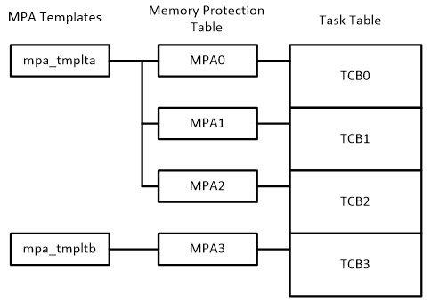
Ralph Moore continues his discussion about using the Cortex-M Memory Protection Unit. Here is part 1. IntroductionAs I noted in my previous blog, "Working With the Cortex-M MPU", embedded systems are being drawn into the IoT and thus security in the form of protection of critical system resources is becoming increasingly important. The previous blog discussed how to define MPU regions and Memory Protection Array (MPA) templates using the regions. How these are used to enable MPU operation in a multitasking environment is the subject of this blog. Task ControlAs shown in the following diagram, there is a Task Table (TT) consisting of a task control block (TCB) for every task that has been created. This table is not in a fixed order, but rather in the order in which tasks are created.
To the left of TT is the Memory Protection Table (MPT). This table has a Memory Protection Array (MPA) for each task. MPAs are in the same order as TCBs and each TCB contains an index into MPT to access its MPA. A task's MPA is loaded into the MPU when the task is dispatched. Thus, each task has its own set of regions when it is running The overhead on task switching time is about 25% for an MPA with 5 regions.. The switching overhead applies to all task switches, whether the MPA changes or not and whether the task is a utask or a ptask. Normally each MPA has at least one dynamic region, the task stack. Other dynamic regions are planned for the future. Thus, loading the MPU on every task switch is necessary. Also, it simplifies MPU usage. MPA TemplatesTo the left of MPT, in the above figure, two MPA templates are shown. How to create MPA templates was covered in my previous blog. Note that tmplta is shared between three MPAs and hence it is shared between three tasks. These tasks comprise a group of tasks that share code and data and are probably part of a subsystem, such as networking or file I/O. Such a task group is comparable to a process in a GPOS system. In a GPOS system processes typically use a Memory Management Unit (MMU) to provide isolation and protection. Here tasks use an MPU for the same purposes. Also shown, tmpltb is used by one MPA and hence by one task. This solitary task can be isolated and protected from all other tasks in the system. Using the example template from the previous blog: const MPA mpa_tmplt_taskA =
{
/*0*/ {RA("ucom_data") | V | S0, RW_DATA | RSI("ucom_data") | EN},
/*1*/ {RA("ucom_code") | V | S1, UCODE | RSI("ucom_code") | EN},
/*2*/ {RA("taskA_data") | V | S2, RW_DATA | RSI("taskA_data") | EN},
/*3*/ {RA("taskA_code") | V | S3, UCODE | RSI("taskA_code") | EN},
/*4*/ {/* taskA_stack */ V | S4, RW_DATA}
};
After taskA has been created, its MPA is loaded with the MPA template as follows: taskA = smx_TaskCreate(taskA_main, 2, 0, 0, "taskA"); smx_TaskSet(taskA, SMX_ST_MPA, mpa_tmpltb_taskA); As previously noted, before taskA starts running, its MPA is loaded into the MPU. As a consequence, taskA can access only the regions shown above and only as permitted by the region attributes. If it tries to access an address outside of the above five regions, a Memory Manage Fault (MMF) will occur. Region attributes are defined as follows; #define RW_DATA XN | RW #define UCODE RO where XN, RW, and RO are MPU attributes that mean execute never, read/write, and read-only, respectively. Hence taskA_data cannot be executed, and taskA_code cannot be written. Nor can taskA access system code or data, nor the code or data of other tasks, unless it shares a region with them, such as ucom_code. Any attempt to do so will cause a MMF. An MMF provides the opportunity to take corrective action, such as stopping the task, rebooting the system, notifying the operator, notifying a remote system, etc. Thus, system takeover by malware can be averted. As a result, system code and mission-critical code are protected from taskA. This level of protection is as good as that achievable with an MMU. Task StacksMPA[4] is reserved for a protected task stack region, which must come from a stack pool so that it can be correctly sized and aligned, as required by the MPU. Stack pool stacks are allocated to tasks when they are dispatched by the scheduler. Following stack allocation, the MPA[4] region is automatically created and loaded by the scheduler. Task stacks are not only protected, but also, task stack overflows are detected and reported as MMFs as soon as they occur. This is helpful for debugging and also blocks a common malware attack method. MPU Background RegionThe MPU background region is like a flood – it breaks down all the barriers in pmode. Consequently, any ptask can access any other ptask's code and data, and even handler and ISR code and data. Also, there is no overflow detection. This is no good. For this reason, I have implemented background region switching. This consists of defining two system regions: sys_code and sys_data. These privileged regions are permanently present in MPU[7] and MPU[6], respectively. Thus, they are present for all tasks and have higher priority than task regions so that overlapping task regions cannot override them. sys_code contains all handler and ISR code and sys_data contains the Main Stack (MS), which is used by handlers and ISRs. The MPU_BR_ON() and MPU_BR_OFF() macros enclose every handler and ISR as follows: SECTION `.sys_code`:CODE:NOROOT
THUMB
smx_SVC_Handler:
smx_MPU_BR_ON
; … SVC_Handler code
smx_MPU_BR_OFF
pop {pc}
MPU_BR_ON() turns the background region ON for handlers and ISRs. MPU_BR_OFF() turns it OFF if the RETTOBASE processor flag is 1 and mpu_br_off global flag is true. The former means that the handler or ISR is not nested and the latter means that the task about to run does not use background mode. mpu_br_off is set when a task is dispatched and its mpav flag is true. A task's mpav flag is set when its MPA is loaded. Each of the above macros is just a few lines of code and add minimal overhead to a handler or ISR. If a handler or an ISR can be entirely contained within sys_code and sys_data, these macros can be omitted - i.e. background region is not turned on for them. Now ptasks can be isolated from other ptasks and handlers and ISRs can be isolated from ptasks. This improves system reliability and is an important stepping stone on the path to utasks. The final MPU structure and a step-by-step procedure to convert existing software to MPU protection will be presented in my next blog. For more information, see www.smxrtos.com/mpu. ralph@smxrtos.com |
||||
| Tidbits | ||||
Kevin Wible passed along this article about a very simple and clever wide dynamic range ammeter that uses the Shockley diode equation to give a logarithmic result. The oscilloscope market has been revolutionized by decent-quality, very low-cost scopes from China. Siglent, Rigol and others offer products with tremendous value for amazing prices. I've wondered how my two favorite scope companies, Tektronix and Keysight (née Agilent, née HP) could compete. Turns out, they can attack on price. Keysight is now offering what appears to be really decent scopes for $450 and up. Several vendors have 3D NAND flash products now. It's quite amazing technology and paints a direction for the continuation of Moore's Law once we stumble into atomic dimensions. Toshiba recently announced a near-term 1TB flash device. It will be a stack of 16 dies using 3-bit MLC. That's a lot of transistors in one package! Note: This section is about something I personally find cool, interesting or important and want to pass along to readers. It is not influenced by vendors. |
||||
| Jobs! | ||||
Let me know if you’re hiring embedded engineers. No recruiters please, and I reserve the right to edit ads to fit the format and intent of this newsletter. Please keep it to 100 words. There is no charge for a job ad. |
||||
| Joke For The Week | ||||
Note: These jokes are archived at www.ganssle.com/jokes.htm. On Engineers, Scientists, and Mathematicians: An engineer, a physicist, and a mathematician are shown a pasture with a herd of sheep, and told to put them inside the smallest possible amount of fence. The engineer is first. He herds the sheep into a circle and then puts the fence around them, declaring, "A circle will use the least fence for a given area, so this is the best solution." The physicist is next. He creates a circular fence of infinite radius around the sheep, and then draws the fence tight around the herd, declaring, "This will give the smallest circular fence around the herd." The mathematician is last. After giving the problem a little thought, he puts a small fence around himself and then declares, "I define myself to be on the outside." |
||||
| Advertise With Us | ||||
Advertise in The Embedded Muse! Over 27,000 embedded developers get this twice-monthly publication. . |
||||
| About The Embedded Muse | ||||
The Embedded Muse is Jack Ganssle's newsletter. Send complaints, comments, and contributions to me at jack@ganssle.com. The Embedded Muse is supported by The Ganssle Group, whose mission is to help embedded folks get better products to market faster. |