|
|
||||||||||||
You may redistribute this newsletter for noncommercial purposes. For commercial use contact jack@ganssle.com. |
||||||||||||
| Contents | ||||||||||||
| Editor's Notes | ||||||||||||
Suppose you're running a 16 bit CPU with a 16 bit timer, but want to accumulate time, in ticks, to more bits. Typically we'd interrupt when the timer overflows and increment a value in memory. When the code needs the time, it concatenates the memory value and the current hardware timer register. About 80% of the code I read that does this is written naively. It works, most of the time, but is guaranteed to fail. This is just one of many subjects covered in my one-day Better Firmware Faster seminar. It delves into technical and process issues to give your team the training they need to operate at a measurably world-class level, producing code with far fewer bugs in less time. It's fast-paced, fun, and uniquely covers the issues faced by embedded developers. Information here shows how your team can benefit by having this seminar presented at your facility. Better Firmware Faster in Australia and New Zealand: I've done public versions of this class in Europe and India a number of times. Now, for the first time, I'm bringing it to Sydney on November 9 and Auckland on November 16. There's more information here. Seating is limited so sign up early. Better Firmware Faster in Maryland: I'm giving this class at The Barr Group's facility in Germantown on November 2, 2015. Firmware practices survey: Are you agile or traditional? Do you track requirements or not? I'm doing a survey of how teams develop firmware. It will take just a minute or two to complete, and I'll share the results in the Muse next month. You have a chance to win one of three copies of "The Embedded Systems Dictionary."
Undecidability is a fundamental limitation that prevents any static analysis tool, no matter how sophisticated, from guaranteeing 100% enforcement of certain types of coding standard rules, or from fully and precisely identifying all instances of certain types of software defects. In this free webinar, Fulvio Baccaglini, Senior Software Developer and member of the MISRA C Working Group, will explain:
Register for our webinar on Wednesday, September 30 |
||||||||||||
| Embedded Video | ||||||||||||
The latest video is a review of the $50 signal generator that was last month's giveaway. The thing has its faults, but offers a lot for fifty bucks. |
||||||||||||
| Quotes and Thoughts | ||||||||||||
The sooner you start to code, the longer the program will take. - Roy Carls |
||||||||||||
| Tools and Tips | ||||||||||||
Please submit clever ideas or thoughts about tools, techniques and resources you love or hate. Here are the tool reviews submitted in the past. |
||||||||||||
| Freebies and Discounts | ||||||||||||
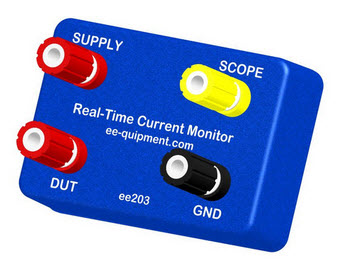
This month I'm giving away a Real-Time Current Monitor, which was kindly provided by ee-quipment. I reviewed it here, and think it's a great tool for measuring current consumption in a system where that changes drastically and frequently, like in a system going in and out of various sleep modes, or sporadically initiating communications. The contest will close at the end of September, 2015. It's just a matter of filling out your email address. As always, that will be used only for the giveaway. Enter via this link. |
||||||||||||
| Prototyping With SMT Components | ||||||||||||
In the last issue a lot of readers wrote in with their techniques for dealing with SMT components. This is a hot topic! Here are some more ideas. Chris Stockbridge wrote:
Paul Carpenter sent this:
Gary Crowell wrote:
Paul Bennett contributed this:
Steve Taylor has a tutorial:
|
||||||||||||
| ARM Assembly Language | ||||||||||||
ARM Assembly Language (Fundamentals and Techniques), by William Hohl and Christopher Hinds, is a 400 page textbook on exactly what you'd expect. While virtually everyone in the embedded world is using C/C++ on ARM processors, a little assembly always seems to creep in. And, we really need to understand a processor's architecture to effectively manage interrupts and the like. As mentioned, this is a textbook, and as such every chapter ends with sample problems. The focus is on the ARM7TDMI and Cortex M4 architectures. This covers a very broad space as the M4 runs a superset of the instructions available on lower-end M-series devices. Thumb and Thumb 2 instructions get as much attention as does the ARM ISA. The book is practical, as it describes the use of the Code Composer and Keil tools. I wish it gave at least some attention to GCC as a lot of developers use those. Three chapters delve deeply into floating point (only one of these covers ARM's floating-point instructions). This is important stuff, as the IEEE-795 format has all sorts of quirks that the authors explore at length. The two chapters (one per ISA) on exception handling are very complete and do cover some of the hardware issues like the fast-interrupt (FIQ). One chapter covers several actual processors and writing code to drive their peripherals. That's probably not useful for us pros, since it's unlikely we'd use the same MCUs, but is appropriate for a university setting where students probably have had little exposure to real hardware. I was surprised, and disappointed, that there's no instruction set summary. Instead, instructions are introduced as needed, rather like one would expect in a college course. But a reference is important, because memories are fallible and combing through 400 pages of text to tease out which instruction you've forgotten is just not efficient. Not all instructions are covered; there's nothing on the SIMD variants. This is a great book for students, and is good for someone just starting out with the ARM parts. But it's no reference, and needs to be supplemented with an ISA summary. It drives me crazy that books are so expensive, and at $86 this is no exception, but the authors have no control over these publishing decisions. |
||||||||||||
| Squaring Square Waves | ||||||||||||
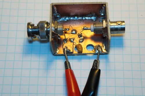
I sometimes need a square wave or pulse signal with really sharp edges. But all of the DDS signal generators I've tested are pretty slow; generally rise times are 10 ns or worse. My most recent video is a review of a $50 unit whose rise time was nearly 40 ns, and the one I used in this example measures 17 ns. So I built the following some time ago to sharpen things up:
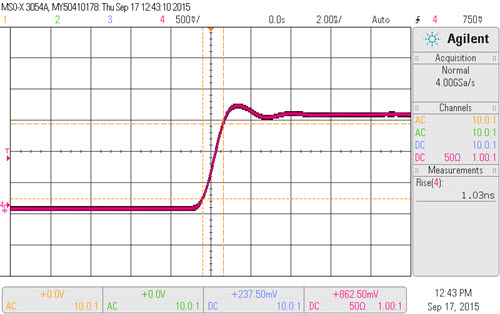
The BNC on the left goes to the signal generator output, and the one on the right is the device's output. The two clip leads go to a power supply. It's basically just a 74AUC1G08 AND gate, which is the fastest TTL gate I can find. TI specs the propagation delay at 0.2 to 1.6 ns at 2.5 volts, but gives no figures for rise time. My MSO-X-3054A scope pegged that at just over a nanosecond:
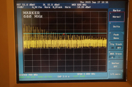
But that is certainly an incorrect reading, as this is a 500 MHz scope. I suspect the rise time is better than the measured value. High-Speed Digital Design, my goto book for all things fast, gives a rule of thumb for frequency components in square waves: F= 0.5/tr, where tr is the rise time, and F is the frequency at which all higher harmonics are at least 40 dBV down. I connected the squarer circuit to my spectrum analyzer, and got this:
In this case 680 MHz is the -40 dBV point. That works out to 735 picoseconds, which is probably closer to the real value than that displayed on the scope. Now, the formula is a rule of thumb rather than a law of nature, but it gives a satisfying result. The 74AUCG08 is powered from a bench supply, but if I were doing it again I'd use a CR2032 battery and a linear regulator. If your signal generator has sluggish transition times, a few bucks worth of parts will really improve its performance. But be careful to set the generator's offset so it produces a waveform that goes from 0 to 2.5 volts, because most will, sans offset, swing equally positive and negative. |
||||||||||||
| Jobs! | ||||||||||||
Let me know if you’re hiring embedded engineers. No recruiters please, and I reserve the right to edit ads to fit the format and intents of this newsletter. Please keep it to 100 words. There is no charge for a job ad. |
||||||||||||
| Joke For The Week | ||||||||||||
Note: These jokes are archived at www.ganssle.com/jokes.htm. Jon Woellhaf sent this: Larry Rachman's great DRAM story (in Embedded Muse 289) reminded me of my favorite board assembly error. When I was a test and repair technician, I happened to notice a diode had been soldered in reversed. But the board tested good! It couldn't, not with that diode reversed, so I investigated. I removed the diode and tested it. It was marked backwards! What is the probability a diode would be marked incorrectly and then installed (by hand) incorrectly? |
||||||||||||
| Advertise With Us | ||||||||||||
Advertise in The Embedded Muse! Over 25,000 embedded developers get this twice-monthly publication. . |
||||||||||||
| About The Embedded Muse | ||||||||||||
The Embedded Muse is Jack Ganssle's newsletter. Send complaints, comments, and contributions to me at jack@ganssle.com. The Embedded Muse is supported by The Ganssle Group, whose mission is to help embedded folks get better products to market faster. |