In the last issue Caron Williams asked how readers build prototypes in this era of incredibly-small components that often don't even have leads. I was inundated with responses. Readers have a number of clever ways to work with these parts. I really appreciate all of the replies.
Sean Newton wrote:
|
This issue continues to manifest for many new prototype or demo board projects especially when working with our MEMS parts where touching the top of the package with a soldering iron will melt the package and ruin the device, as well as those stubborn QFN packages found on many power components. Having the right tools makes it much easier to deal with small board assemblies.
Here is a solution that has helped with our prototype boards:
* Buy an inexpensive programmable reflow oven such as the T962 Infrared IC Heater (~$200)
* Buy a stencil for your board (~$60-100 per board design depending on the size of your board) and a squeegee (such as https://www.stencilsunlimited.com/).
* Buy solder paste (keep it cool).
* Get a decent microscope for part placement and alignment.
* Place in the oven and bake.
It is well worth the extra cost of the oven, stencil and solder paste versus the frustration of hand soldering which could result in ruined devices and boards. We have been very pleased with how well this process works on our small prototype boards.
As far as your question on WLCSP packages, I don't recommend them for prototype unless you can afford the assembly costs. I would suggest asking the device manufacture for a like product in a better package which sometimes this is just not possible. Otherwise a BGA rework station will help to do the job -- here is a nice video I found showing the process: https://youtu.be/slOhcdmbFJU.
|
Romain Bazile said:
|
In my (very small) company, we use a cheap and fast turnaround service for making small batches of prototyping boards. Basically, we just spend a few minutes (hours depending on the complexity of the design) designing what we need (breakout boards with needed passives, or full fledged test boards).
We then send everything to some boards houses (OSHPark and DirtyPCBs both have good records for us, and they know how to work fast if you're willing the pay $50-$100 to get your boards fast!) and also to OSHStencil to get our stencils laser-cut from Kapton film.
Then, it's just a matter of hand-doing paste spreading, component population and off to the reflow oven.
On that last part, ours cost us less than $100. We bought a cheap oven from any appliance store you can find, and repurposed it with an SSR, an Arduino and a shield on it and a thermocouple in the oven.
You cook your board, and then you just need to finish but hand-soldering through-hole components that are left.
All in all, it takes me less than 2 weeks to design and build small boards (the longest being the lead time on the boards themselves). I've gotten very consistent results with this process.
And for very tiny footprints... Better train a little and have a steady hand (or a repurposed 3D printer that can do component population on a board... But this needs a lot more prep work!)
|
Chris Deckard also likes OSH Park and OSH Stencil:
|
I found using OSH Park and OSH Stencil has helped me get proof of concept boards in a time frame and budget that is reasonable. I have a fine pitch soldering iron (Hakko FX-951), a low cost hot air gun (Tenma ~$50), a used binocular microscope from Ebay ($100), and a good pair of tweezers allows me to assemble PCBs at a reasonable rate (I've even managed on those tiny AD 2x4 BGAs).
Not the same as a breadboard, but these services bring what used to cost in the kilobucks down to the hectobucks.
|
Robert Lange goes straight to PCB:
|
Your 289 newsletter mentioned the difficulties of using breadboards with today's SMT parts.
I almost never use breadboards anymore - you can get PCB's cheap and fast these days from the right places. One service I have used is http://www.pcbway.com/. On that site you specify the size, quantity, layers, copper thickness, etc and upload a GERBER file. Once it passes a file audit you pay for it (I use PayPal) and they start fabrication.
For example, I recently ordered 10 boards from PCBway (86x56mm, 2 layer, 2 oz copper, with solder mask and silk screen). It was $64 total for 48 hour production and another $25 for DHL 3-5 day shipping for a total of $89. I placed the order on June 25th and had 10 PCBs in my hand on the 30th.
$8.90 a board in 5 days? How can you beat that?
And as an addendum, a 2-4X microscope does wonders for soldering most small SMT components (except BGA parts). It takes some practice but if you have solder paste, flux, and very thin solder, it only takes a few boards to become reasonably proficient.
|
Jason Long wrote:
|
I'm typically a silent reader of the Embedded Muse but wanted to chime in on the question from Caron regarding breadboarding and building prototype circuit boards.
Though the answer is "it depends on many factors" the first spin of boards that we do is always at a low-run board house and we hand populate them when they come in. I use one of two sources for low-run quantities of PCBs: Alberta Printed Circuits (www.apcircuits.com) which will get you 2 layer soldermask + overlay boards in a few days or OSHPark (www.oshpark.com) which averages about a week as long as you courier the boards (if you're not in a rush, they offer free snail mail shipping world wide). Both are very reasonably priced.
I've always hand-populated the first two boards of any design I've done -- I can still manage to solder down to 0402 with good success even after 15 years! While some people may balk at the thought of this, I ALWAYS learn something extremely valuable from going through and populating these parts. It forces you to do a detailed BOM and schematic review part-by-part, and doubles as a preliminary check for manufacturability to catch parts that are maybe too close or any unintended asymmetric heat-sinks. And of course if you've screwed up a footprint or something else, you get to figure that out instead of an SMT house trying to run your boards. Regardless, I assure you this beats trying to breadboard!
The "it depends" factors in for BGAs but in most cases there is a non-BGA variant of the IC and I don't think getting an exact form-factor PCB is necessary for rev 1. If you have a board that is THAT stringent, I think you're stuck with the reality of that development cost. In this case, it's great to poke around and find a local SMT place that can do prototype runs at reasonable cost, but of course that's going to be a minimum of $1k just for the stencil and machine time. Another unavoidable reality.
The last issue is parts. I think Digi-key is the de facto go-to for small quantities if you're hand-populating. Building up a well-organized parts library is essential here, as is paying attention to minimizing new parts on designs. E.g. make sure everyone specifies the same 3.3V LDO (assuming that there are no particular special needs). If you have to machine-populate, you hit another reality of having to supply those parts in reels, but you can mitigate this as expensive parts can usually be fed on cut-tape, Digi-key offers "Digi-reels" for a nominal surcharge, and a contract manufacturer might be able to hand-place really special parts if you're nice to them. What's great is that passives are now sub-$10 per reel, so keeping stock isn't going to break the bank (but still see the note on maintaining a standard library of parts -- an LED on your prototype doesn't care if it's got a 1k or 1.2k resistor in front of it!).
For a bit of a pitch: we specialize in working with companies who are exactly in Caron's position - I'd be happy to chat with anyone with this dilemma about options, strategies, training or some contract help.
|
John Taylor sent a couple of emails about this. I've consolidated them to this:
|
I've been doing all of the prototyping at my company and home projects and have had great success down to 0.8mm pitch BGAs. I use multi layer boards from a vendor in China, paste masks from Quick Stencil, lead free solder paste from Kester, solder spreaders from Home Depot and a toaster oven for reflow. Parts cost is 60-90% of the cost of a prototype run and turn around is 3 to 5 days. The picture is a rack of boards about to get soldered:
Another great tool to get is a hot-air soldering tool. I like the Saike 858.. With the hot air tool, you tin the pads, flux the pads, set the part and then apply heat until the solder melts. It's amazing how surface tension make the process very tolerant of my old age
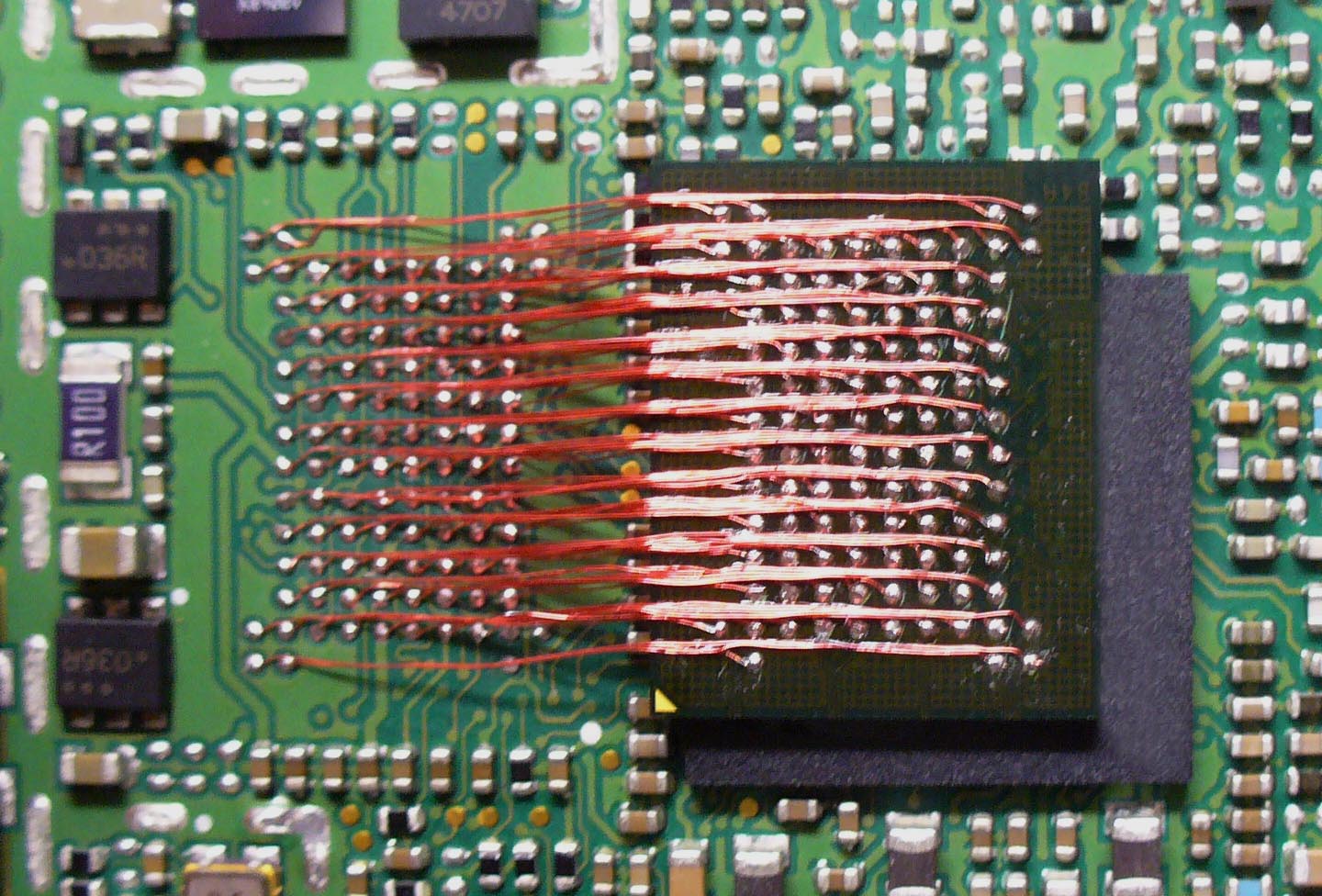 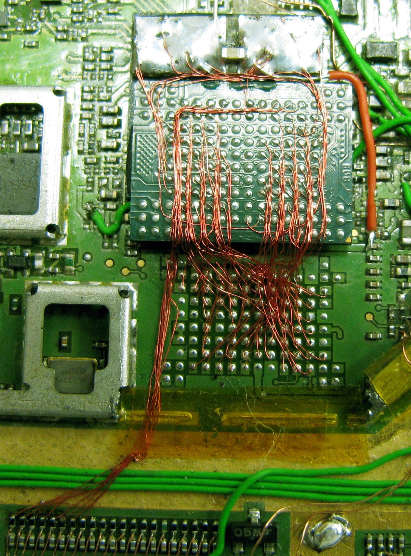
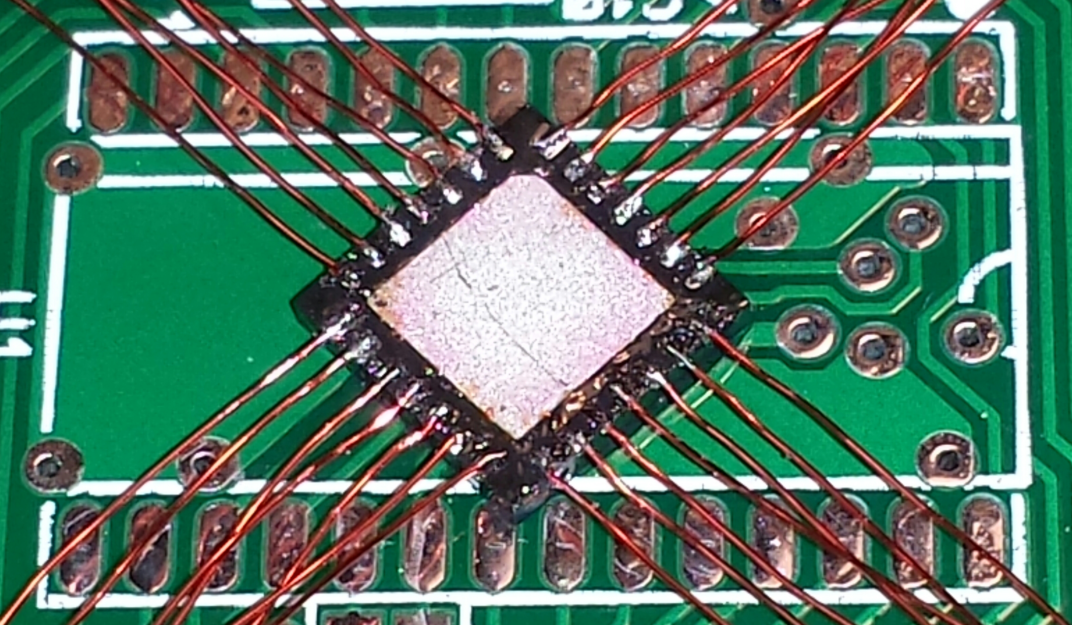
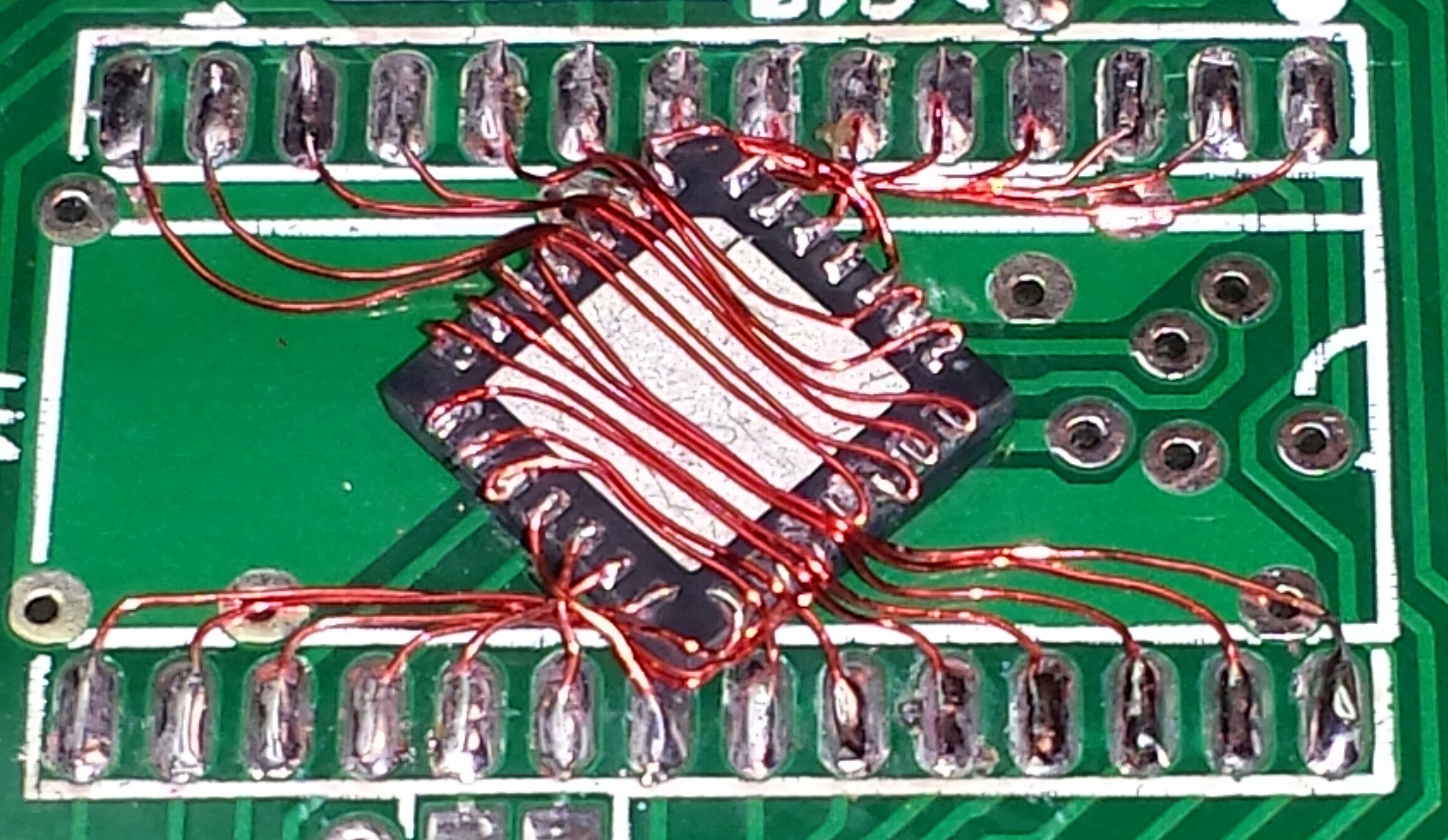
The first picture is a 0.5mm pitch BGA stacked NAND flash/200MHz DDR RAM that I dead bugged so that we could get to buried signals in a 6 layer micro-via phone board for debugging the memory interface when I worked at Kyocera Wireless. We did the same thing when we wanted to test memories from other vendors with new pinouts before we would commit to spinning a variant PWB (See second picture). That is #43 wire done with a Hakko soldering... I used the same large tip for everything and would only replace it after it was completely eroded past the steel jacket into the copper core!
Note: Both of these ran first time! Here are a couple of more examples:
|
Juha Kuusama wrote:
|
In The Embedded Muse 289, Caron Williams put a question: "We are finding it increasingly difficult to make bread boards and test them..." and you have the same issue: "Amen to this question. I have some ADP172 voltage regulators from Analog Devices here. They're 1 mm square in a WLCSP with four balls. I can barely see the devices, let along solder them!"
As I see it, to solve the issue you have to learn how to do SMD circuit boards in-house. This sounds much more involving that it actually is, and has become easy and economical in last few years: You need CAD tools; free and good tools exist, and paid tools start from peanuts. This would be a subject of its own; for this discussion, it is sufficient to note that the difficulty is selecting which tool to use, not tool availability. Then, you need the actual circuit boards. In recent years, competition has driven the cost of prototyping boards down to almost nothing, although speed vs. cost is still somewhat an issue. Putting solder paste on the board using a stencil is trivial work, even by hand. This is really as easy as the video on page http://www.beta-estore.com/rkuk/order_product_details.html?p=13 shows, even when doing it the first time. Then, you put the components on the board either manually using a good stereo microscope or if that is too much work, using a machine*. And finally, you'll solder the board in a reflow oven. I use the oven in the above link. It is really a cheap pizza oven, but for prototyping purposes, quite enough with a good controller. You do need a controlled temperature profile for good results. Not an issue either, the controller costs less than a good soldering iron.
So, I encourage you and your readers to take the plunge to get SMD prototype assembly capabilities in-house. It only takes a few hundred and couple of days and really makes a difference in your lab! You can read my experiences with the above mentioned kit at http://dangerousprototypes.com/forum/viewtopic.php?f=2&t=4471.
*: Once you can do prototyping in house, you might find that manually placing the parts can be the bottleneck, depending on the boards you make. Some parts are painfully small to handle manually, especially if there are many. When you can do SMD assembly, you would be tempted to do prototypes for a full product in-house. At some point, manual component placement is just too tedious. I did one board with 450 parts manually, and decided not to do that ever again! I was very surprised not to find any prototyping pick and place machines on the market. I honestly thought I would spend an evening on the Internet just selecting what machine to buy, but found nothing. So, I did my own. Being an entrepreneur, noticing that I would have paid a couple of thousands for a tool and finding nothing even close on the market, I took the extra effort to make it commercially available. You can read the story at http://www.liteplacer.com/about/the-story/.
Today, the pick and place machine is available as a DIY kit for $1299 USD or 1199 Euro at http://www.liteplacer.com/.
|
Larry Marks commented:
|
You wrote "Amen to this question. I have some ADP172 voltage regulators from Analog Devices here. They're 1 mm square in a WLCSP with four balls. I can barely see the devices, let along solder them!"
If I had one or two of these, I'd just use the old "dead bug" approach. Solder a piece of wire-wrap wire to each ball, glue the device to the breadboard upside-down and connect the flying leads. But doing a whole breadboard like this would be crazy. And I can't even imagine doing a 9x9 or 11x11 breadboard that way.
|
Tim Wescott has a strategy:
|
My coping strategies for this situation are:
* Modular design
* Lots of simulation
* Lots of test points
* Evaluation boards from chip vendors
* Circuit board aggregators for in-house eval boards and first articles.
Most of the comments are based on analog circuit design. When I design circuit boards for customers, they're usually a whole lot of analog content with a processor in the middle pulling all the strings. FPGA designers have their own disciplines -- which aren't terribly different in general from what I'll babble about below, but which are different in detail.
Modular Design:
Do this in hardware for the same reason you do it in software: so that you can verify in isolation, and so that when you find that a module is hopeless, you can cut it out and replace it.
Lots of simulation:
This is obvious -- if you know how a part should work, then you can simulate a circuit before you build a circuit board. It is scary to go into a new circuit board design with only simulation data and analysis -- but it works.
In a sense, extensive analysis and simulation of your circuit blocks plays the same role in a good hardware design as extensive UML-ing and unit testing does in good software design -- it makes sure that you have a good chance of success before you start putting things together.
Simulation can get challenging if you're using a microcontroller + code as an analog component, but you learn how to simplify that part of the simulation so that you can still get meaningful results. It mostly boils down to refraining from trying to simulate the whole thing, and rather committing to simulating bits of it and then patching together a whole using analysis of the results.
Lots of test points:
Simulation only works to the extent that your model matches the reality -- and models never match reality. The mismatches can come about because you didn't understand the problem, or they can come about because the part's data sheet (or the manufacturer's SPICE model) did not reflect the reality.
So when I design, I try to toss in lots of test points. Recently I've discovered that you can get test points the size of an 0603 surface-mount resistor (I think there's smaller ones, too). Putting these at critical spots in the circuit does wonders.
Evaluation boards from chip vendors:
Chip vendors often sell eval boards for the chips that they're most proud of. This is almost universally true for FPGA and microprocessors, but there's quite a population of ADC, DAC, and other chips out there, too. I mine this resource as necessary.
Circuit board aggregators:
If you can schedule your project correctly, and if you can keep the layer count down to no more than four, you can get boards made quite economically by circuit board aggregators. My favorite one is OshPark (www.oshpark.com). They're friendly, and they use US factories. I've had circuit designer friends sneer at them because "a 4 layer board is hobby stuff", but unless you're doing super high-speed digital, four layers is usually enough to do your own "evaluation" board, and two is often enough. OshPark will charge you $5 per square inch for a two-layer design; it'll deliver three boards to your door for that price. The price you pay for the low price is time: they take up to two weeks to deliver, and their four-layer board service is slower yet.
If you're in a hurry, the prices for quick turn small boards from places like www.sunstone.com aren't all that bad compared with the additional time it takes to mess around with bread boards, and you can generally achieve much better signal integrity (which, in turn, leads to a lot less expensive messing around). If you're paying your assembly tech a living wage you may find that it's actually cheaper to make 1st-cut "breadboards" using a quick-turn house than it is to have him spend his time roping circuits together from the old-style breadboards.
|
Scott Murphy likes Scgmartboard:
|
I've never actually used these, but saved the link in case the opportunity/need came along. Schmartboard makes a line of patented fan-out boards including SMT-to-DIP adapters that are (potentially) easy to solder. Prices per piece run from about $1 to $10, depending on complexity. |
Dave Stumbo wrote:
|
I'm sure you'll get this from lots of readers, but: http://www.proto-advantage.com/store/ .
In addition to the products they show, they can also buy and solder the chips down for you. I got 2 breakout boards for ADCs made that way for ~ $35 for the pair plus the cost of the ICs. |
David Wright passed this on:
|
Re. the recent comment about bread-boarding of increasingly small chip packages, we recently made use of a vendor of ready made boards suggested by a hardware engineer colleague: http://www.proto-advantage.com/.
They supply bare boards, and will mount chips on the boards for a price (e.g. http://www.proto-advantage.com/store/product_info.php?products_id=4000001).
Naturally this gave us an invaluable head start on the software before the real hardware was available. |
Finally, Joe Cisneros had a suggestion, and an entirely novel use for heat sinks:
|
I can't imagine what the pad looks like for a millimeter sized chip. But...
For things almost visible to the naked eye I use a hot plate and a thermometer. I've had some success soldering LEDs to heat sink plates using this method. I burned a few getting started, there wasn't even a wisp of magic smoke. I recommend starting at about 350 Fahrenheit.
P.S.
Heat sinks are great for thawing out meat.
|
|