

Review of Zeroplus's LAP-C Logic Analyzer
Last October I reviewed Zeroplus's LAP-F1 logic analyzer. That is a high-end product that offers pretty much any feature you could ask for. The company also sent me one of their more affordable units, the LAP-C, AKA the Logic Cube.
The LAP-C comes in a number of flavors with prices from $139 for 16 channels and 32k bits of memory per channel, up to $2,149 for a unit with 32 channels and 2 mb/channel. I evaluated the most expensive and capable unit in the lineup.
The software UI is Windows-only, and Windows 7 is recommended. The manual states that "uncertified workaround exists" for Windows 8.1 and 10; I used the latter and had no problems. Various on-line reviewers cite installation difficulties, but the software installed painlessly for me.
First, the specs:
- Sample rate: Internal clock 100 to 200 MHz, depending on model (from manual: "Remember that the sample rate should be at least 4 times higher than the DUT signal frequency for the sampling to be accurate."
- External clock: 75 to 100 MHz, depending on model.
- Memory: 32 Kb to 2 Mb per channel, depending on model
- # channels: 16 or 32
- Threshold voltage: settable from -6 to 6 v with a 0.1V resolution
- Triggers: state, edge or pattern
- Trigger sequence levels: 1
- Trigger pass counter: 65535
- Input impedance: 500 KΩ, 10 pF
- Protocol decoders: > 120 included. Some models can trigger on protocol comm
- Powered by the host PC's USB. The unit pulls 500 mA.
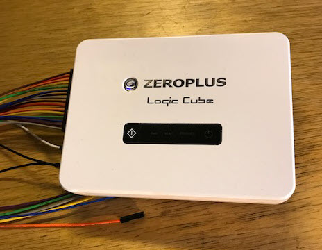
The unit is small and is in a nice-looking plastic box. There's not much to the hardware; a LED lights up when it's powered and a single button can command captures. Another LED illuminates when it is acquiring data, another when the data is being sent to the PC, and yet one more lights when a trigger event occurs.
It came with a complete set of cables and hookup clips.
The user interface is a little intimidating at first. Pretty much everything can be controlled from the quick-access toolbar. The waveform display shows fairly tiny signals, at least to my old eyes. I wished I could make them bigger in the vertical dimension. Turns out, they can be any size you'd like. In fact, the font size selector is right there on the quick-access toolbar. Pretty much everything on the screen can be configured: font size, colors, shortcut keys, tool bars, etc.
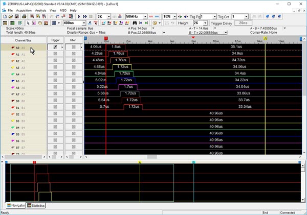
The user interface.
Note all of controls on the quick-access toolbar. Below that, a strip reads out cursor information. Below that is the waveform display, which is a zoomed in portion of the data. The bottom windows is the complete set of data. To the left are the signal names, followed by trigger and filter controls.
Navigation is very fast as are screen updates. Even when acquiring 2 million bits for each of the 32 channels, the upload to the PC took only 5 seconds. Drop that to 256 kb/channel and the upload is under a second.
The mouse scroll wheel pans the waveforms left and right.
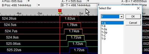
In the picture above the red cursor (vertical line) is the trigger. A and B cursors are enabled for measuring signals, and you can add up to 250 more. Above the waveform display a strip shows the positions and deltas of three cursors. The next picture shows this, and a drop-down menu that lets you select which cursors (I've added a few) are shown in that strip.
The UI has a built-in screen capture which I thought was a little silly as we all have such tools. Except you can add an annotation, which is pretty sweet if you're saving a lot of screen shots and need to know what each one consists of.
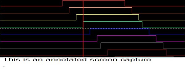
Screen shot with annotation
You do have to re-specify if you want a complete screen (you won't - it's the entire desktop) or a region, and if you don't want to save it to a file, instead putting it on the clipboard. I wish it had remembered my prior selection.
Or, you can export the data to a text or .CSV file. If the former, the file contains all the analyzer's setup information. There are a lot of options to limit the data - for instance, it can export only changes in data, or particular busses.
With logic analyzers it's all about the memory. The LAP-C is nice in that it can filter signals to use less of that resource. That is, samples are stored only when certain user-defined signals are high or low. And, one can add a delay so signals are filtered for a period after the filter condition is satisified.
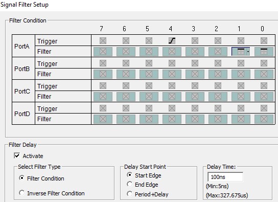
Signal filters
Compression is another memory-saving feature. When enabled it will compress the data, in real-time, by a factor of up to 256, depending on how fast the signals change. It's off by default as rapidly-changing signals could net a negative compression ratio.
For units with 32 channels, a "double mode" is available when sampling 16 or fewer inputs. This mode uses the memory normally dedicated to the 16 unused channels to double the acquisition memory.
Triggering is not terribly sophisticated (for incredible triggering see the LAP-F1 model I mentioned earlier). It will trigger on edges and levels, and pattern-trigger on as many channels as you'd like. Triggers are easy to set up. In the first screen shot above, next to each signal name there's a box. Click on it to cycle through triggering modes.
A trigger delay causes the LAP-C to store data a certain time after the trigger event occurs. If, as in the following picture, the "Memory Delay" is selected, the unit starts acquiring data after a multiplier of the memory depth has happened. So if the memory depth is set to 32 kb, and the multiplier to 10, then the analyzer starts to store samples after 320 kb of data has happened. I'm not entirely sure what the value of this feature is.
However, one can also set a delay based on time: delay acquisition until so many ns after the trigger, or so many clock cycles have occurred.
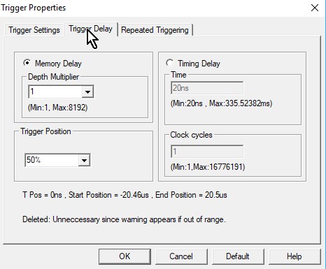
Trigger delay
Like a lot of these USB logic analyzers there's no way to trigger on pulse widths. But a $100 optional (included on the highest-end unit) add-on will enable triggers on times between edges, or triggers on a specified duration of a signal.
Some of the USB analyzers will only do a single-shot acquisition. The LAP-C allows repeated acquisitions; after filling the memory and displaying the results it reacquires another memory-load, repeating till you hit the stop button.
An output goes high when the unit is sucking in data. Connecting that to a scope, I found that with the shortest buffer (2 kb) it reacquires every 500 ms, rising to 1.6 s for a 512 kb buffer, and to 5 s for 2 mb. This was with a 50 MHz acquisition rate so the actual reading of data from the target board was a tiny percentage of these numbers.
I don't like that I can't scroll left and right through the waveform when the unit is repeatedly acquiring.
A nifty feature is the ability to show busses as analog data. Suppose you're monitoring the inputs to a DAC. Tell the LAP-C to group those into a bus, and then display both the digital signals and an equivalent analog representation, like this:
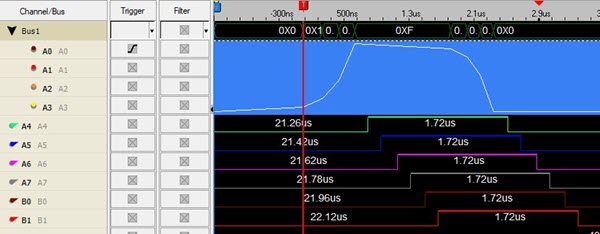
Note signals A0 to A3 are grouped into a bus. The numeric bus value is in the top line, below that (in blue) is the equivalent value as an analog waveform.
Another intriguing feature is the ability to filter noise and other gunk from the display. For instance, a bus that is transitioning may be in some uninteresting and distracting state. You can tell the LAP-C to ignore transitions that are shorter than some period. The range for the filter is 20 ns to 1.3 ms. In the state mode another filter can eliminate signals that are shorter than some number of clocks; the allowed range goes from one to 200 clocks.
As with most logic analyzers the user can specify the numeric base for displayed data. Generally analyzers support decimal, binary, and hex. The LAP-C handles those, but adds ASCII and, of all things, Gray code. I don't run into the latter much anymore, but occasionally it is useful. Some encoders output Gray. With Gray code only a single bit changes at a time. The code is useful in, among other things, electromechanical systems where not all contacts will change at exactly the same time; with a binary code this can lead to momentary incorrect counts.
Binary |
Gray |
00 |
00 |
01 |
01 |
10 |
11 |
11 |
10 |
When counting in Gray Code only one bit changes at a time
My overall impression of the LAP-C is very positive. The UI is fast and responsive, and reasonably intuitive, though I did read through the entire manual. It makes good use of the function keys. And, for the fashion-conscious, it comes with a very nice hard zip-up carrying case which could be the ultimate in nerd accessorizing.