

USB Scopes and Logic Analyzers, by Jack Ganssle
Traditional scope vendors have greatly shrunk the size of their offerings. Some of Tektronix's products are a third the space of their predecessors. Yet when saddled with a display and sea of controls there are limits to how small , and how inexpensive, these units can ever be. But for developers and students looking for smaller and cheaper instruments there are a number of palm-sized units that substitute a USB connection and the PC's screen for the CRT. Some offer astonishing performance. All are brilliantly designed and utterly cool.
Written March, 2005. I have also reviewed some other, more recent, instruments here.
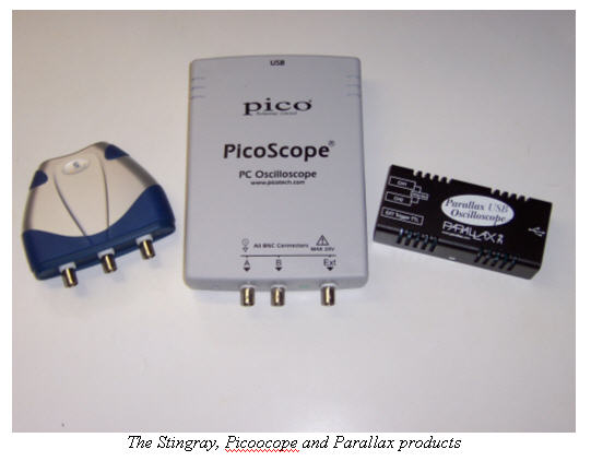
I decided to evaluate some of these USB "microscopes" to how the units compare to traditional bench scopes. And later in this document I review USB logic analyzers. I looked at offerings from Parallax, Saelig/USB Instruments, Picotech and Bitscope. These are all digital storage oscilloscopes (DSO) and offer more features than traditional analog models. I'll review the Bitscope next month as it's a cross-dressing scope/logic analyzer combo.The users' manuals (some printed, some only on disk) and help files were uniformly awful. Though none of the units were hard to use, the documentation served as an effective barrier to understanding.
Only Parallax's unit came with any sort of probes because a decent one can easily run $100. Plenty of vendors do sell less expensive probes, but buy warily as a poor choice can distort signals and may be shoddily constructed.
None of these scopes offer the same ranges as your desktop Agilent or Tektronix. Feed more than a few tens of volts into the inputs and the smoke detectors will smother your yell of rage. But with a x10 probe that's still enough range to work with most circuits found in embedded systems.
| Suggestion: Subscribe to my free newsletter which often has reviews of hardware and software tools. |
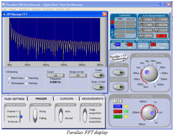
These DSOs can apply a Fast Fourier Transform to the signals to rotate amplitude data to the frequency domain, creating a useful spectrum analyzer mode.
All but one will save captured data to disk. My bench scope is nearly always connected to the PC for the very same reason, which makes me scratch my head and wonder if it's not possible to use a virtual instrument all of the time.
Parallax USB Oscilloscope
For $149 you can't expect much. At least that's what I thought till the Parallax (www.parallax.com) unit arrived, professionally packaged in a blister pack as part of an "Understanding Signals" kit. The iPod-sized scope alone is $129.
The unit isn't designed to meet the need of the serious developer, but it packs an awful lot of punch for the price. Two channels plus an external TTL trigger, 1 million samples per second when using a single channel, half that when both are on. It has a 200 KHz bandwidth with 8 bits of vertical resolution and a +/- 20 volt input range.
All of the other units I'll review have standard BNC input connectors. The Parallax scope, though, uses .157" cylindrical connectors and comes with crude probes. Eighteen inches of non-coaxial cable terminates in standard clip leads. But perhaps this is a reasonable tradeoff given the unit's 200 KHz bandwidth.
The USB host (PC) provides power to the scope. Don't try to run the device from an unpowered hub.
Installation was trivial, taking under a minute. There's no uninstall, which is sort of a nuisance when evaluating many different devices.
The GUI is simply beautiful and looks a lot like the front panel of an ordinary bench scope. Two big knobs control the vertical scale and time base. Drag them with the cursor. The single vertical does double duty for both input channels; I'd prefer two knobs.
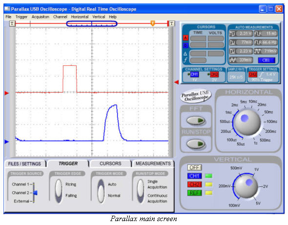
Trigger the unit from either channel or the external input (which is a digital signal, not analog). The trigger level is a slider that puzzled me at first requiring my only trip into the help file.
Very easily-adjusted horizontal and vertical cursors appear on the screen. Position them with the mouse and the GUI will measure time, voltage, frequency and deltas.
Though all of the scopes were responsive, this one took my breath away. Updates at reasonable sample rates were instantaneous. One visitor noted that it took forever to update the screen . . . and then realized he was sweeping at 1 sec/div, requiring 30 seconds for a single acquisition.
At $129 this sounds like a toy scope, but the only toy-like features are the 200 KHz bandwidth and simple probes. I'd recommend the Parallax unit for low-speed applications, educational use, and to get your kids interested in electronics. At audio frequencies this is all the scope you'll ever need. The very well-thought out "Understanding Signals" kit for $20 more, plus a BASIC Stamp microcontroller, will teach newbies about scopes and analog and digital circuits. The kit's manual is on-line at http://www.parallax.com/dl/docs/prod/sic/Signals.pdf.
Stingray
UK-based USB Instruments (http://www.usb-instruments.com) manufactures the Stingray, which is sold in the USA by Saelig Instruments (http://www.saelig.com/) for $220. For some reason the documentation calls it the "EasyScope II".
The Stingray's case is as sexy as its name, a streamlined wedge smaller than a CD. It comes in a faux-leather pouch which can hold a couple of probes as well as the instrument. They must have hired a marketing person from Apple.
The unit has two channels which accept +/- 50 volt signals, and an external trigger input that takes an input in the +/- 3.5 volt range. The analog bandwidth is 250 KHz with one million samples per second in single-shot mode, or 20 million for repetitive signals. Inputs are sampled with 12 bit resolution into a 32 Kb buffer, which works out to 8 K samples per channel. A nice feature lets one reduce the buffer depth to 1 K for faster updates at slow sweep rates.
The difference between 8 and 12 bit resolution is palpable. Ramps look significantly smoother. For high precision analog work I'd go with the 12 bits.
Installation was easy but a little odd; it seems to install twice, once per channel. Thankfully an uninstall is included. Help is adequate - barely - and very concise.
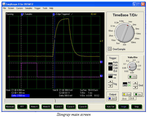
The GUI is, if possible, even prettier than Parallax's, though cursor, FFT and meter buttons across the bottom are a bit clunky-looking. Again, two big knobs set vertical and horizontal ranges. And again, I'd sure prefer separate knobs for the two vertical channels. The cursors are particularly simple to use.
But the trigger adjustment is cumbersome. Though it looks like a slider, one must click repeatedly on up/down buttons to adjust the level. A knob or real slider would be a big improvement.
The Stingray's external trigger is apparently a TTL input. The GUI lets you trigger on a rising or falling edge of this signal.
Like the Parallax unit, the Stingray is very responsive. Change a setting and the screen updates with new data immediately.
Though the datasheet suggests the unit has a delayed timebase function, I couldn't find any reference to this in the documentation, or on-screen controls to use such a function.
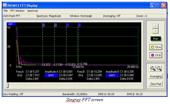
Easy-to-use horizontal and vertical cursors measure amplitude and time, though not frequency. You can enable up to 6 digital meters that display instantaneous, peak or RMS voltage, and frequency. That might be useful in a production environment where the technician must make routine measurements.
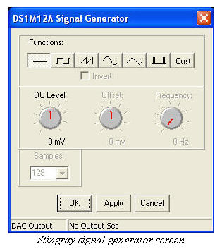
Interestingly, the external trigger input can also function as an output for a signal generator. The unit will generate sine, square, triangle, ramp and even custom waveforms you design yourself. It's limited to audio frequencies only, and the waveforms are more than a little rounded, so don't toss your bench signal generator. But for those on a tight budget with limited needs this is a handy feature.
PC-hosted instruments can have functionality limited only by the imagination and software. In this case an "EasyLogger" feature captures data and displays it like a strip chart recorder (remember those?) and to a file.
The bottom line: 250 KHz bandwidth is too narrow for most of us working on the digital end of an embedded system. But if your processor is slow (and a lot are) or you need a handy scope for routine analog work, this device will suit most users fine. Slip it into your pocket for travel and have fun convincing the TSA folks that the device isn't a threat to national security.
Picoscope 3206
Picotech (http://www.picotech.com) has a very broad line of PC-hosted DSOs, ranging in price from a $132 (at current exchange rates) one-channel 20 KHz model to the $1535 top of the line 3206 that I tested. Other 3000-series units have similar features at lower bandwidths and buffer sizes, priced at $766 and up. The Picoscope moniker is unfortunate as this unit offers mega performance.
The 3206 is somewhat larger than the others I looked at, but at 5" x 7" x 1.5" could still fit comfortably in a purse. It requires an external wall transformer, and does not have a power switch.
The software comes with an uninstall, a welcome addition since it took a couple of tries to get the software to recognize the DSO. But once running it performed flawlessly.
Picotech is UK-based, which perhaps explains why I wrestled so hard with the 82 page .pdf manual. As one wag noted, we're two peoples divided by a common language, which in this case means Norteamericanos will glean little of use from the documentation. Since "tips" don't appear when mousing over menus I spent a lot of time in the not terribly helpful help file.
The input range is +/- 20 volts for both channels and the external trigger input.
A 200 MHz analog bandwidth and 100 million samples/second data collection (200 million when using only one channel) makes the 3206 quite the speed demon. On repetitive signals it'll suck in an effective 10 billion samples/sec. In all modes it has 8 bits of vertical resolution, and a 1 meg data buffer. The trigger can be positioned at any point in the buffer, a very important feature needed to capture pre- and post-trigger events.
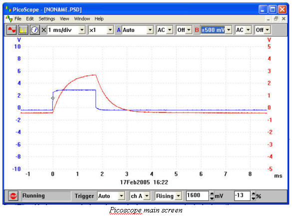
The GUI makes no attempt to imitate the knobs on a traditional scope. It's somewhat clumsier than the other user interfaces, though the signals are displayed with a hard-to-describe but breathtaking clarity. This interface is all about the displayed data, not the controls.
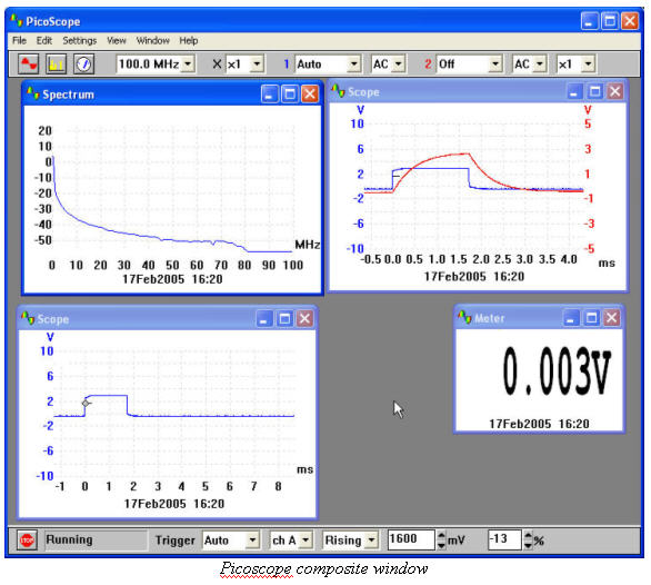
The unit is very responsive and has fast screen updates.. . except when there's a spectrum analyzer window and one or more scope views open at the same time. Then things get sluggish. Close a window and the speed issues disappear.
A zoom feature that expands and pans through the deep 1 meg buffer works well, and is very fast. Suppose you capture a signal with the time base set to 50 msec/division and need to look at an edge in more detail. Just zoom . . . and zoom . . . and zoom, up to 1000x, without recapturing.
A single mouse click selects the two horizontal and vertical cursors (confusingly called "rulers" in the help file) which enable the usual spectrum of measurements. But Picotech adds much more - you can display averages and even standard deviations of the data, and can select which parts of the signal contribute to the calculations. Displaying a color burst or swept waveform? Measurements on most scopes are meaningless since the frequency varies across the screen. On the 3206 just pop up a dialog to select where to take data.
Variable persistence lets signals stay on-screen forever or fade from view after a specified time. In digital color mode areas of the trace that repeat frequently are red; those that don't head towards the blue. It's easy to spot infrequent events like a glitch.
The 3206's internal signal generator creates sine, square and triangle waves at speeds to 1 MHz. Under 500 KHz frequency their frequency stability was 1% or better; above 500 KHz stability degenerated.
This is a fast scope with a deep buffer that's useful for real work on real embedded systems. It's a reasonable substitute for some bench instruments, and is great for travel.
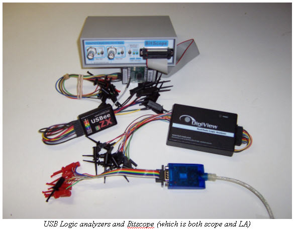
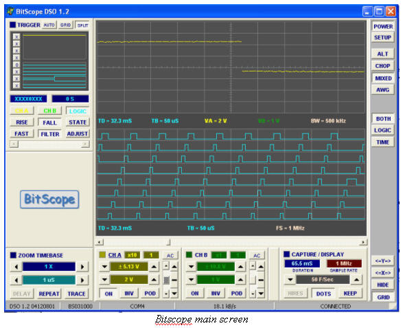
BitScope
BitScope (www.bitscope.com) offers products ranging in price from $295 to $1495. I looked at their $495 model 310.
This instrument is a hermaphrodite, a Mixed Signal Oscilloscope (MSO) that's both 8 channel logic analyzer and two-input DSO. MSOs shine in the embedded world where digital and analog signals interact in strange and mysterious ways. An MSO will display both domains on the same screen, and can trigger on either a digital condition or at some analog voltage level. There's no better way to see how the logic and analog relate.
The BitScope comes with a real, printed users' manual that, while lacking detail - actually an awful lot of detail - includes the unit's schematics. There's no help file.
It requires 12 volts from an external power supply, which isn't a wall wart but is the preferable in-line design with a cord that plugs into the wall. There's no power switch, unfortunately. The unit is housed in a solid aluminum powder-coated case which feels very substantial for such a small (6" x 4" x 2") device.
The specs are impressive. Analog bandwidth is 100 MHz, though the A/D's is 75 MHz. A note explicitly claims "[the] BS300 includes compensation for this convertor (sic) to achieve 100 MHz bandwidth throughout." I'm not sure what that means. Max sample rate is 40 Msps (million samples per second), a departure from usual scope specifications where the analog bandwidth is several times lower than the sample rate. But the BitScope uses a single flash A/D multiplexed between the two channels dumping data into a 128Ks (kilosample) deep buffer. 8 digital channels go into their own 128Ks buffer.
The A/D has 6.8 to 7.6 effective bits of resolution. At lower speeds the software averages data boosting resolution to either 9.5 bits (according to the manual) or 11.5 (from the web site). Max input voltage is 5.5 with a X1 probe. Get a decent X10 and you'll be able to probe most embedded systems without loading the signals unduly.
Use caution when comparing the BitScope's resolution to other units. I can't help but wonder if these conservative figures result from very careful characterization of the A/D and analog front end. The schematics show the company put a lot of care into the analog design, borne out by the unit's performance. Linearity and distortion were nearly perfect even at high sweep rates.
Installation was trivial, and an uninstall program is included.
There's no way to save waveform data to a file yet, though I'm told that's coming in version 1.3 of the software, due out about when this article appears.
The unit's variable 0 to 50 usec trigger holdoff is a very useful feature that prevents early retriggering. And the delayed sweep feature is a boon for people searching for events that occur long after the trigger. When enabled the sweep doesn't start till some user-entered time elapses after the trigger. In the olden days delayed sweep came with dual timebases and triggering systems; this seems less common today even on bench scopes, which is a pity. But no one would expect this level of capability on a $495 scope.
Triggering is quite powerful, and a zoom/pan mechanism makes it easy to slide around in the deep data buffer. I couldn't figure out how to center the trigger, though, so it appears there's no way to look at pre-trigger events. The trigger level is displayed in a small version of the scope window (upper left hand side of the figure) and is hard for these 51 year old eyes to see. I'd prefer a line drawn on the main screen, as on most conventional DSOs. There's no explicit external analog trigger, though it's easy to use one of the digital inputs as such.
The GUI is moderately pretty, though not quite as intuitive or as simple as described for the scopes evaluated last month. Bench-type knobs are replaced with typical Windows controls which work well, but break the oscilloscope paradigm. Coupled with the poor manual it's sometimes hard to figure out how to use the deep set of features embedded in the hardware.
Screen updates are very, very fast, running up to 50 frames/second. But then occasionally unpredictable and annoying delays hang things up. Window's system monitor shows the code isn't burning CPU time so perhaps there's some communications glitch.
Changing settings sometimes maddeningly resets the vertical gain and time base settings to default values. Anything that increases the engineer's workload is a bad idea. All in all, the software has the feel of not being quite done yet.
In analog alternate mode the max sweep rate is 10 nsec/division, which falls to 50 nsec in chop. When displaying mixed signals (digital and analog at the same time) the maximum is 25 nsec/div.
I was a little disappointed to find the BitScope can only show one of its two analog channels when the digital signals are on the screen.
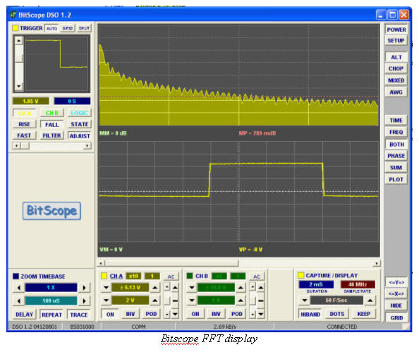
A very nice spectrum analyzer display looks almost too uncluttered at first . . . there are no labels on the axis. Yet moving the vertical cursor displays mdB clearly.
Interestingly, the unit has a replaceable external pod. As supplied it samples 5 volt signals; a different pod will handle 3 volt logic.
An arbitrary waveform generator can turn analog channel B into an output for sine, square or ramps. Below 1 MHz the signal integrity is reasonable; above that frequency distortion is severe.
There are no analog probes, not surprising for such an inexpensive unit. The digital clips are of medium quality; you'll never get them onto an SMT pin, though with a bit of cunning will manage to connect to through-hole IC leads.
This is a well-made hardy unit. The analog design received a lot of attention. It's almost instrument-quality. I'd really like to see pre-trigger data, and the occasional data drop outs were annoying, but if the new software fixes most of those problems I'd love to have this unit in my toolbox.
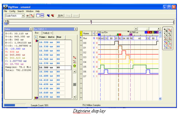
DigiView
Techtools' (http://tech-tools.com) $499 DigiView logic analyzer samples 18 channels into a 128Ks buffer. It's a palm-sized unit in a simple but rugged plastic box that will slip into your shirt pocket. Power comes from the USB connection, so don't run this from an unpowered hub. The company claims it will work with 2 to 5 volt logic, though I didn't test this.
Software installation was trivial, though no uninstall was included. Help is quite poor; you'll have to fiddle with the thing to figure it out. That's unfortunate as it's a quite innovative design which could benefit from a bit more descriptive information.
The DigiView doesn't have a sweep control of any sort, giving an uncluttered display that accentuates the acquired data. It always sucks in data at 100 MHz, which would swamp the buffer in a mere millisecond in a conventional unit. But hardware compresses the data in real time so that 128 Ks buffer goes a lot further. My test setup generated 8 channels of staggered 10 usec pulses. The DigiView managed to acquire 79 million samples of this, or _ of a second. That's an awful lot of data, but of course your mileage will vary depending on the input signals.
The device took 1.5 seconds to upload the compressed buffer.
One of the DigiView's strengths are extensive search features, needed to manage such a deep virtual buffer.
With the fixed 10 nsec sampling rate, there's no external clock.
The supplied clip leads are of good quality, and are fine for working with large-pitch SMT devices. But the colors of the wires are off - channel 0 is brown, instead of black, as is standard on most instruments, since black corresponds to zero in the resistor color code.
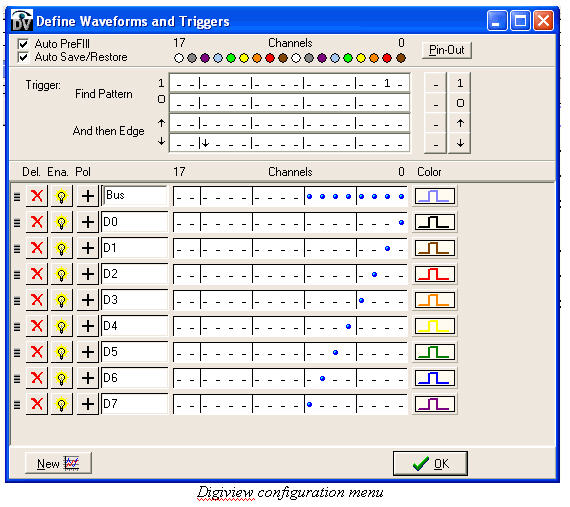
In the configuration menu above I've enabled only 8 of the possible 18 channels, and have configured them as individzual signals as well as a bus. The previous screen shot shows data acquired as both the bus and as separate signals.
Though the GUI will save data in CSV format, it won't snag a graphical screen shot. Me, I like the screen shots to illustrate technical documents though plenty of third party programs will capture Windows screen images.
Overall I'd call the DigiView an interesting, well-built unit with good mechanical engineering (box, wires, clips). It sucks in an awful lot of data both in width (18 channels) and depth. The GUI is pretty easy to navigate.
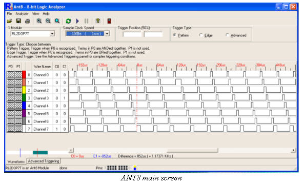
ANT8
USB Instrument's (http://www.usb-instruments.com) ANT8 logic analyzer is the 8 channel baby brother to their ANT16 word-sized unit. It's sold in the USA by Saelig (http://www.saelig.com) for a mere $222.
Taking a cue from Apple the device has a see-through case, that doesn't seem to quite fit correctly around the USB cable. This unit will fit inside your pocket protector, and is powered from the USB host. I peered through the plastic and found a half-dozen ICs, one of which is a Xilinx Spartan FPGA. Presumably many of these analyzers have new FPGA equations downloaded to configure triggers, which is pretty cool engineering.
The datasheet seems to suggest that the device is tailored for 5 volt logic.
I was never able to successfully install the software on my PC despite numerous attempts and reboots, though it worked flawlessly on the laptop. The documentation is for a Windows 98 environment, though was easy enough to adapt to XP.
Where some of the other units have deep buffers, the ANT8's is a fairly tiny 3072 samples, that uploads instantaneously to the PC. The unit's upside is speed: it will acquire at up to 500 MHz, a breathtaking rate for such a tiny and inexpensive device.
If there's a provision for an external clock, I couldn't find it.
The exceedingly easy-to-use UI was very intuitive and almost made up for the woeful help file. You can save data (in CSV or a proprietary ASCII format ) but not screen images.
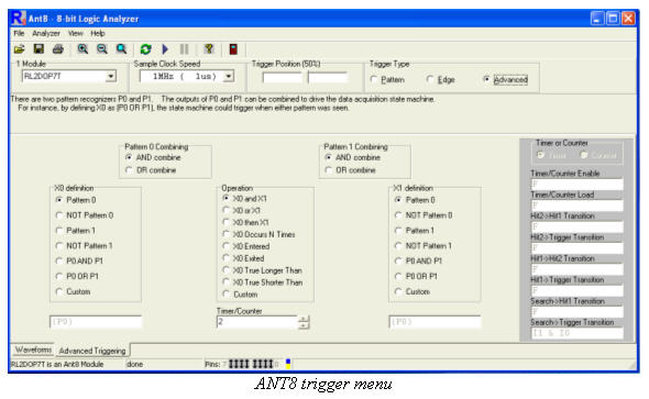
Triggering is astonishingly versatile. It's simple to set basic triggers on the main screen, but a tab pops up the advanced triggering screen that can look for durations, number of events (with a 10 bit counter), and interactions between two patterns. This screen, too, is well designed and immediately updates to gray out choices no longer valid as you configure the trigger.
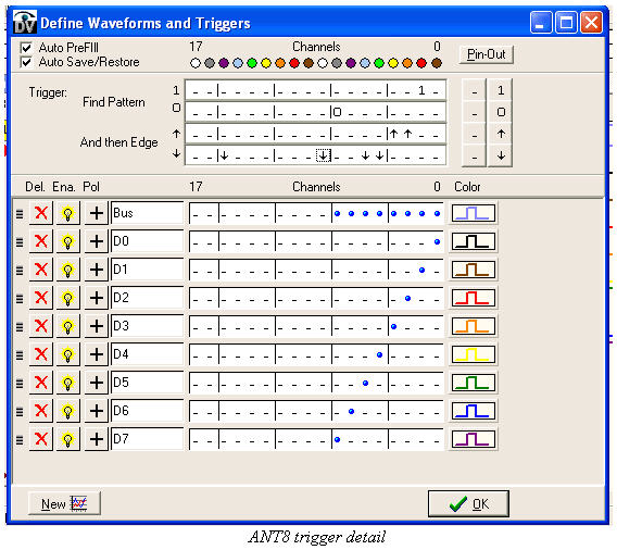
The clip leads simply couldn't be worse. Sure, this is a very inexpensive device and and decent clips are expensive. A few inches of cheap ribbon cable sprout from the logic analyzer and are terminated by a cauliflower-head of clips that appear to come from the local Radio Shack. Happily they'll surely break with just a little use, giving you the chance to build a better cable with real clips. Where on the DigiView the colors were shifted one from the resistor code, on the ANT8 they're moved two positions, so red is bit 0.
With all of the leads in a single ribbon cable, and no grounds between wires, I worry that at high speeds crosstalk could possibly corrupt the signals enough to cause incorrect displays. or even effect the operation of the system being tested.
My gut feel: the unit looks like a toy, sucks in data like an Oreck vacuum, has a buffer as shallow as a tidal pool, and is as easy to use as an iPod. None of the other units came close in triggering capability. If you replaced the confounded probes it would make a nice travel tool.
USBee ZX
USBee's (http://www.usbee.com) USBee ZX is the high-end of a family of 8 channel logic analyzers ranging in price from $295 to $895. It's hard to compare this unit to the others as it has some philosophical differences, starting with the two 15 minute videos that step one through the device's operation. There's no help file in the conventional sense; help only - and annoyingly - calls up snippets of the video. Some of the features are, near as I could find, undocumented, though most are pretty intuitive.
Though it's usually powered through the USB cable, provision has been made to attach an external 3.3 or 5 volt supply. The documentation doesn't state logic levels, but it's reasonable to assume that when powered by 3.3V it will correctly handle those signal levels. It does require USB 2.0 and will not work with 1.1.
The unit will acquire at rates to 24 Msps, and stores, near as I could understand, a million samples in the on-board buffer. But it fires data to the PC at USB 2.0's blistering rates so can stack samples on the PC in real time. My fast PC gave a virtual buffer of almost 500 Ms. And this all happens very seamlessly; there are no noticeable delays.
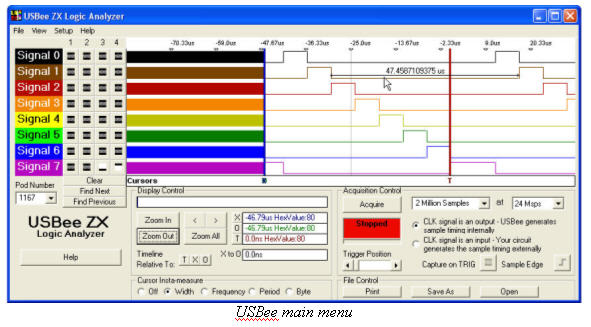
The UI is simple and reasonably easy. On the left hand side there's four trigger levels which offer plenty of capability but aren't nearly as extensive as, say, those on the ANT8. In the picture note that two of channel 7's conditions are combined to trigger on a high-going edge.
This is the only unit reviewed with a dedicated external trigger input, and it has an external clock as well. The supplied clips were the best of all of the analyzers.
The USBee isn't really a logic analyzer per se; it's more a collection of tools. There's a 75 KHz frequency counter. A 1 MHz frequency generator, an I2C controller and much more. The signal generator is particularly interesting as you can save waveforms captured by the logic analyzer, edit them, and then replay the data out the clip leads. A ToolBuilder suite lets the user create new tools altogether, which is a pretty cool idea.
The USBee has a simple UI, it's easy to configure triggers, is ultra-portable, and most importantly offers an interesting degree of extensibility.
Summary
The old-timer in me still yearns for knobs, whether a scope's time base control or a sextant's knurled micrometer. There's something ineffably satisfying about reaching for a physical control that virtual instruments can't beat. When you're buried in the bowels of a big PCB it's easier to twist a knob than mouse around a screen.
But these USB instruments offer an astonishing amount of performance for little cost. Some will satisfy the lab requirements for many real embedded development efforts. And for traveling I'd grab one of these in a heartbeat rather than a conventional 20 pound all-in-one scope or logic analyzer.
Which one is best? That's impossible to say. I'd sure like the Picoscope's 12 bit A/D combined with the BitScope's MSO, the DigiView's 18 channels, and the ANT8's triggering. For training purposes it's hard to beat Parallax's $129 scope or ANT8's $222 analyzer.