

A Guide to Debouncing - Part 2, or, How to Debounce a Contact in Two Easy Pages
By Jack Ganssle
Hardware Debouncers
Part 1 of this article shows how contacts bounce, with oscilloscope screenshots, and how to debounce them in software. This part describes hardware debouncers.
Figure 1 shows the classic debounce circuit. Two cross-coupled NAND gates form a very simple Set-Reset (SR) latch. The design requires a double-throw switch. Two pull-up resistors generate a logic one for the gates; the switch pulls one of the inputs to ground.
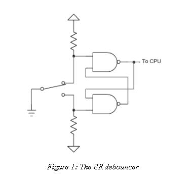
The SR latch is a rather funky beast, as confusing to non-EEs as recursion is to, well, just about everyone.
With the switch in the position shown the upper gate's output will be a one, regardless of the value of the other input. That and the one created by the bottom pull-up resistor drives the lower NAND to a zero . . . which races around back into the other gate. If the switch moves between contacts, and is for a while suspended in the nether region between terminals, the latch maintains its state because of the looped back zero from the bottom gate.
The switch moves a rather long way between contacts. It may bounce around a bit, but will never bang all the way back to the other contact. Thus, the latch's output is guaranteed bounce-free.
The circuit suggests an alternative approach, a software version of the same idea. Why not skip the NAND pair and run the two contracts, with pull-ups, directly to input pins on the CPU? Sure, the computer will see plenty of bounciness, but write a trivial bit of code that detects any assertion of either contact. which means the switch is in that position, as follows:
             if(switch_hi())state=ON;
             if(switch_lo())state=OFF;
switch_hi and switch_lo each reads one of the two throws. Other functions in the program examine variable state to determine the switch's position.
This saves two gates but costs one extra input pin on the processor. And, it requires a double-throw switch. But it's the simplest - and most reliable - debounce code possible.
The MC14043/14044 chips consist of four SR flip flops, so might be an attractive solution for debouncing multiple switches.
An RC Debouncer
The SR circuit is the most effective of all debouncing approaches. but it's rarely used. Double-throw switches are bulkier and more expensive than the simpler single-throw versions. An awful lot of us use switches that are plated onto the circuit board, and it's impossible to make DP versions of these. So EEs prefer alternative designs that work with cheap single-throw switches.
Though complex circuits using counters and smart logic satisfy our longing for pure digital solutions to all problems, from signal processing to divorce, it's easier and cheaper to exploit the peculiar nature of a resistor-capacitor (RC) network.
Charge or discharge a capacitor through a resistor and you'll find the voltage across the cap rises slowly; it doesn't snap to a new value like a sweet little logic circuit. Increase the value of either component and the time lag ("time constant" in EE lingo) increases.
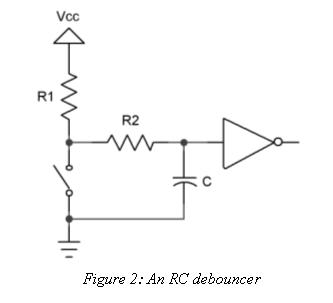
Figure 2 shows a typical RC debouncer. A simple circuit, surely, yet one that hides a surprising amount of complexity.
Suppose our fearless flipper opens the switch. The voltage across the cap is zero, but it starts to climb at a rate determined by the values of R1, R2 and C. Bouncing contacts pull the voltage down and slow the cap's charge accumulation. If we're very clever in selecting the values of the components the voltage stays below a gate's logic one level till all of the whacking and thudding ceases. (If the time constant is too long, of course, the system won't be responsive to fast switch actuations).
The gate's output is thus a pristine bounce-free logic level.
Now suppose the switch has been open for a while. The cap is fully charged. Snap! The user closes the switch, which discharges the cap through R2. Slowly, again, the voltage drools down and the gate continues to see a logic one at its input for a time. Perhaps the contacts open and close a bit during the bouncing. While open, even if only for short periods, the two resistors start to recharge the cap, reinforcing the logic one to the gate. Again, the clever designer selects component values that guarantee the gate sees a one until the clacking contacts settle.
Squalid taverns are filled with grizzled veterans of the bounce wars recounting their circuits and tales of battles in the analog trenches. Most will puzzle over R2, and that's not entirely due to the effects of the cheap booze. The classic RC debouncer doesn't use this resistor, yet it's critically important to getting a thwack-free output from the gate.
R2 serves no useful purpose when the switch opens. R1 and C effectively remove those bounces. But strange things can happen when suddenly discharging a capacitor. The early bouncing might be short, lasting microseconds or less. Though a dead short should instantly discharge the cap, there are no pristine conditions in the analog world. The switch has some resistance, as do the wires and PCB tracks that interconnect everything.
Every wire is actually a complex circuit at high speeds. You wouldn't think a dull-headed customer flipping the switch a few times a second would be generating high-speed signals, but sub-microsecond bounces, which may have very sharp rise times, have frequency components in the tens of MHz or more. Inductance and stray capacitance raises the impedance (AC resistance) of the closed switch. The cap won't instantly discharge.
Worse, depending on the physical arrangement of the components, the input to the gate might go to a logic zero while the voltage across the cap is still one-ish. When the contacts bounce open the gate now sees a one. The output is a train of ones and zeroes - bounces.
R2 insures the cap discharges slowly, giving a clean logic level regardless of the storm of bounces. The resistor also limits current flowing through the switch's contacts, so they aren't burned up by a momentary major surge of electrons from the capacitor.
Another trick lurks in the design. The inverter cannot be a standard logic gate. TTL, for instance, defines a zero as an input between 0.0 and 0.8 volts. A one starts at 2.0. In between is a DMZ which we're required to avoid. Feed 1.2 volts to such a gate and the output is unpredictable. But this is exactly what will happen as the cap charges and discharges.
Instead use a device with "Schmitt Trigger" inputs. These devices have hysteresis; the inputs can dither yet the output remains in a stable, known state.
Never run the cap directly to the input on a microprocessor, or to pretty much any I/O device. Few of these have any input hysteresis.
Doing The Math
The equation for discharging a cap is:
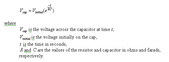
The trick is to select values that ensure the cap's voltage stays above Vth, the threshold at which the gate switches, till the switch stops bouncing. It's surprising how many of those derelicts hanging out at the waterfront bars pick an almost random time constant. "The boys `n me, we jest figger sumpin like 5 msec". Shortchanging a real analysis starts even a clean-cut engineer down the slippery slope to the wastrel vagabond's life.
Rearranging the time constant formula to solve for R (the cost and size of caps vary widely so it's best to select a value for C and then compute R) yields:
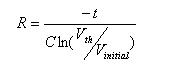
Though it's an ancient part, the 7414 hex inverter is a Schmitt Trigger with great input hysteresis. Some AHCT versions have worst case Vth for a signal going low of 1.7 volts. Let's try 0.1 µF for the capacitor since those are small and cheap, and solve for the condition where the switch just closes. The cap discharges through R2. If the power supply is 5 volts (so Vinitial is 5), then R2 is 185K. Of course, you can't actually buy that kind of resistor, so use 180K.
But. the analysis ignores the gate's input leakage current. A CMOS device like the 74AHCT14 dribbles about a microamp from the inputs. That 180K resistor will bias the input up to .18 volts, uncomfortably close to the gate's best-case switching point of 0.5 volt. Change C to 1 µF and R2 is now 18K.
R1 + R2 controls the cap's charge time, and so sets the debounce period for the condition where the switch opens. The equation for charging is:
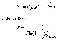
Vfinal is the final charged value - the 5 volt power supply. Vth is now the worst-case transition point for a high-going signal, which for our 74AHCT14 a peachy 0.9 volts. R1 + R2 works out to 101K. Figure on 82K (a standard part) for R1.
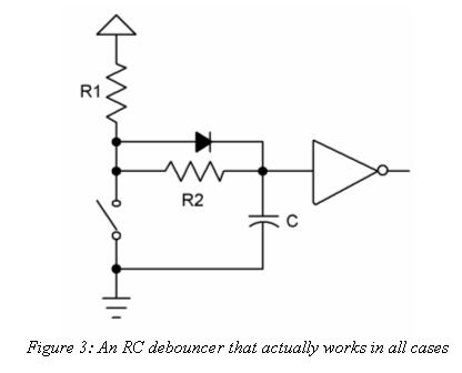
The diode is an optional part needed only when the math goes haywire. It's possible, with the wrong sort of gate where the hysteresis voltages assume other values, for the formulas to pop out a value for R1 + R2 which is less than that of R2. In this case the diode forms a short cut that removes R2 from the charging circuit. All of the charge flows through R1. The previous equation still applies, except we have to account for drop across the diode. Change Vfinal to 4.3 volts (5 minus the 0.7 diode drop), turn the crank and R1 pops out.
Be wary of the components' tolerances. Standard resistors are usually ±5%. Capacitors vary wildly - +80/-20% is a common rating for electrolytics. Even small ceramics might vary ±30%.
Other Thoughts
Don't neglect to account for the closed resistance of oddball switches. Some conductive elastomer devices exceed 200 ohms.
Two of the elastomer switches I examined didn't bounce at all; their output smoothly ramped from zero to +5 volts. The SR and RC debounce circuits are neither necessary nor effective. Better: run the switch directly into a Schmitt Trigger's input.
Never connect an undebounced switch to the clock of a flip-flop. The random bounce hash is sure to confuse the device. A 74HCT74 has a max rise and fall time spec of 6 nsec - easily exceeded by some of the data I acquired from the 18 switches tested.
The 74HC109 requires a minimum clock width of 100 nsec. I found pulses shorter than this in my experiments. Some of these parts, like from Philips, have a Schmitt Trigger clock input - it's a much safer part to use when connected to real-world events.
Similarly, don't tie undebounced switches, even if Schmitt Triggered, to interrupt inputs on the CPU. Usually the interrupt pin goes to the clock input of an internal flip flop. As processors become more complex their datasheets give less useful electrical information; they're awash in programming data but leave designers adrift without complete timing specs. Generally we have no idea what the CPU expects as a max rise time or the min pulse width. Those internal flops aren't perfect, so don't flirt with danger by feeding them garbage.
The MC14490 is a cool chip that consists of 6 debouncers. A datasheet is here. But in August of 2004 Digikey wants $5.12 each for these parts; it's cheaper to implement a software debounce algorithm in a PIC or similar sub-$1 microcontroller.
Always remember to tie unused inputs of any logic circuit to Vcc or ground.
Debouncing in Firmware
Software debounce routines range from the utterly simple to sophisticated algorithms that handle multiple switches in parallel. But many developers create solutions without completely understanding the problem. Sure, contacts rebound against each other. But the environment itself can induce all sorts of short transients that mask themselves as switch transitions. Called EMI (electromagnetic interference), these bits of nastiness come from energy coupled into our circuits from wires running to the external world, or even from static electricity zaps induced by shuffling feet across a dry carpet. Happily EMI and contact whacking can be cured by a decent debounce routine. . . . but both factors do affect the design of the code.
Consider the simplest of all debouncing strategies: read the switch once every 500 msec or so, and set a flag indicating the input's state. No reasonable switch will bounce that long. A read during the initial bounce period returns a zero or a one indicating the switch's indeterminate state. No matter how we interpret the data (i.e., switch on or off) the result is meaningful. The slow read rate keeps the routine from deducing that bounces are multiple switch closures. One downside, though, is slow response. If your user won't hit buttons at a high rate this is probably fine. A fast typist, though, can generate 100 words per minute or almost 10 characters per second. A rotating mechanical encoder could generate even faster transitions.
But there's no EMI protection inherent in such a simple approach. An application handling contacts plated onto the PCB is probably safe from rogue noise spikes, but one that reads from signals cabled onto the board needs more sophisticated software, since a single glitch might look like a contact transition.
It's tempting to read the input a couple of times each pass through the 500 msec loop and look for a stable signal. That'll reject much or maybe all of the EMI. But some environments are notoriously noisy. Many years ago I put a system using several Z80s and a PDP-11 in a steel mill. A motor the size of a house drawing thousands of amps drove the production line. It reversed direction every few seconds. The noise generated by that changeover coupled everywhere, and destroyed everything electronic unless carefully protected. We optocoupled all cabling simply to keep the smoke inside the ICs, where it belongs. All digital inputs still looked like hash and needed an astonishing amount of debounce and signal conditioning.
Debounce Policy
There are some basic constraints needed on our anti-contact-clacking routines. Minimize CPU overhead. Burning execution time while resolving a bounce is a dumb way to use processor cycles. Debounce is a small problem and deserves a small part of the computer's attention.
The undebounced switch must connect to a programmed I/O pin, never to an interrupt. Few microprocessor datasheets give much configuration or timing information about the interrupt inputs. Consider Microchip's PIC12F629 (datasheet at http://ww1.microchip.com/downloads/en/DeviceDoc/41190c.pdf). A beautiful schematic shows an interrupt pin run through a Schmitt Trigger device to the data input of a pair of flops. Look closer and it's clear that's used only for one special "interrupt on change" mode. When the pin is used as a conventional interrupt the signal disappears into the bowels of the CPU, sans hysteresis and documentation. However, you can count on the interrupt driving the clock or data pin on an internal flip flop. The bouncing zaniness is sure to confuse any flop, violating minimum clock width or the data setup and hold times.
Try to avoid sampling the switch input at a rate synchronous to events in the outside world that might create periodic EMI. For instance, 50 and 60 Hz are bad frequencies. Mechanical vibration can create periodic interference. I'm told some automotive vendors have to avoid sampling at a rate synchronous to the vibration of the steering column.
Finally, in most cases it's important to identify the switch's closure quickly. Users get frustrated when they take an action and there's no immediate response. You press the button on the gas pump or the ATM and the machine continues to stare at you, dumbly, with the previous screen still showing, till the brain-dead code finally gets around to grumpily acknowledging that, yes, there IS a user out there and the person actually DID press a button.
Respond instantly to user input. In this fast-paced world delays aggravate and annoy. But how fast is fast enough?
I didn't know so wired a switch up to the cool R3000 starter kit Rabbit Semiconductor provides. This board and software combo seems targeted at people either learning embedded programming or those of us who just like to play with electronical things. I wrote a bit of simple code to read a button and, after a programmable delay, turn on an LED. Turns out a 100 msec delay is quite noticeable, even to these tired old 20/1000 eyes. 50 msec, though, seemed instantaneous. Even the kids concurred, astonishing since it's so hard to get them to agree on anything.
So let's look at a couple of debouncing strategies.
A Counting Algorithm
Most people use a fairly simple approach that looks for n sequential stable readings of the switch, where n is a number ranging from 1 (no debouncing at all) to seemingly infinity. Generally the code detects a transition and then starts incrementing or decrementing a counter, each time rereading the input, till n reaches some presumably safe, bounce-free, count. If the state isn't stable, the counter resets to its initial value.
Simple, right? Maybe not. Too many implementations need some serious brain surgery. For instance, use a delay so the repetitive reads aren't back to back, merely microseconds apart. Unless your application is so minimal there are simply no free resources, don't code the delay using the classic construct: for(i=0;i<big_number;++i);. Does this idle for a millisecond. or a second? Port the code to a new compiler or CPU, change wait states or the clock rate and suddenly the routine breaks, requiring manual tweaking. Instead use a timer that interrupts the CPU at a regular rate - maybe every millisecond or so - to sequence these activities.
Listing 1 shows a sweet little debouncer that is called every CHECK_MSEC by the timer interrupt, a timer-initiated task, or some similar entity.
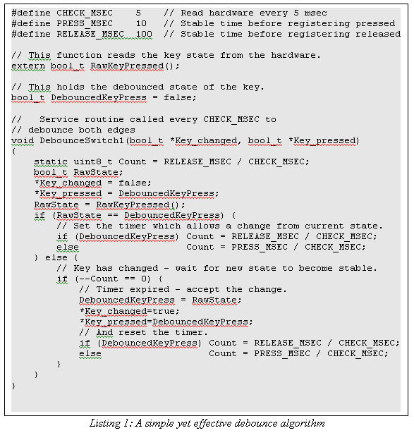
You'll notice there are no arbitrary count values; the code doesn't wait for n stable states before declaring the debounce over. Instead it's all based on time and is therefore eminently portable and maintainable.
DebounceSwitch1() returns two parameters. Key_Pressed is the current debounced state of the switch. Key_Changed signals the switch has changed from open to closed, or the reverse.
Two different intervals allow you to specify different debounce periods for the switch's closure and its release. To minimize user delays why not set PRESS_MSEC to a relatively small value, and RELEASE_MSEC to something higher? You'll get great responsiveness yet some level of EMI protection.
An Alternative
An even simpler routine, shown in figure 2, returns TRUE once when the debounced leading edge of the switch closure is encountered. It offers protection from both bounce and EMI.
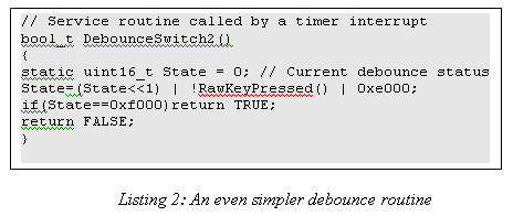
Like the routine in listing 1, DebounceSwitch2() gets called regularly by a timer tick or similar scheduling mechanism. It shifts the current raw value of the switch into variable State. Assuming the contacts return zero for a closed condition, the routine returns FALSE till a dozen sequential closures are detected.
One bit of cleverness lurks in the algorithm. As long as the switch isn't closed ones shift through State. When the user pushes on the button the stream changes to a bouncy pattern of ones and zeroes, but at some point there's the last bounce (a one) followed by a stream of zeroes. We OR in 0xe000 to create a "don't care" condition in the upper bits. But as the button remains depressed State continues to propagate zeroes. There's just the one time, when the last bouncy "one" was in the upper bit position, that the code returns a TRUE. That bit of wizardry eliminates bounces and detects the edge, the transition from open to closed.
Change the two hex constants to accommodate different bounce times and timer rates.
Though quite similar to a counting algorithm this variant translates much more cleanly into assembly code. One reader implemented this algorithm in a mere 11 lines of 8051 assembly language.
Want to implement a debouncer in your FPGA or ASIC? This algorithm is ideal. It's loopless and boasts but a single decision, one that's easy to build into a single wide gate.
Handling Multiple Inputs
Sometimes we're presented with a bank of switches on a single input port. Why debounce these individually when there's a well-known (though little used) algorithm to handle the entire port in parallel?
Figure 3 shows one approach. DebounceSwitch(), which is called regularly by a timer tick, reads an entire byte-wide port that contains up to 8 individual switches. On each call it stuffs the port's data into an entry in circular queue State. Though shown as an array with but a single dimension, a second loiters hidden in the width of the byte. State consists of columns (array entries) and rows (each defined by bit position in an individual entry, and corresponding to a particular switch).
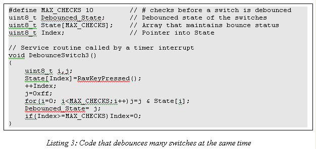
A short loop ANDs all column entries of the array. The resulting byte has a one in each bit position where that particular switch was on for every entry in State. After the loop completes, variable j contains 8 debounced switch values.
One could exclusive OR this with the last Debounced_State to get a one in each bit where the corresponding switch has changed from a zero to a one, in a nice debounced fashion.
Don't forget to initialize State and Index to zero.
I prefer a less computationally-intensive alternative that splits DebounceSwitch() into two routines; one, driven by the timer tick, merely accumulates data into array State. Another function, Whats_Da_Switches_Now() ANDs and XORs as described, but only when the system needs to know the switches' status.
Trent Cleghorn implemented this very nicely in C and C++. The code is here.
Here's another, well documented, approach to debouncing: http://www.kennethkuhn.com/electronics/debounce.c .
In June of 2021 Eric Nelson sent this approach:
Consider the following, that only ever changes the debounced pin state if the pin has been stable for 40ms. //
// Idea courtesy Ganssle Group. Called from a 5ms timer,
// the debounced state only ever changes when the pin
// has been stable for 40ms. Initialize debounced_state
// to whatever is "inactive" for the system (HIGH or LOW)
//
uint8_t DebouncePin(uint8_t pin)
{
static uint8_t debounced_state = LOW;
static uint8_t candidate_state = 0;
ĀĀ candidate_state = candidate_state << 1 | digitalRead(pin);
if (candidate_state == 0xff)
debounced_state = HIGH;
else if (candidate_state == 0x00)
debounced_state = LOW;
return debounced_state;
} |
Summing up
All of these algorithms assume a timer or other periodic call that invokes the debouncer. For quick response and relatively low computational overhead I prefer a tick rate of a handful of milliseconds. One to five msec is ideal. Most switches seem to exhibit under 10 msec bounce rates. Coupled with my observation that a 50 msec response seems instantaneous, it seems reasonable to pick a debounce period in the 20 to 50 msec range.
Hundreds of other debouncing algorithms exist. These are just a few of my favorite, offering great response, simple implementation, a no reliance on magic numbers or other sorts of high-tech incantations.
Thanks to many, many people who contributed suggestions and algorithms. I shamelessly stole ideas from many of you, especially Scott Rosenthal, Simon Large, Jack Marshall and Jack Bonn.
(Please use proper engineering analysis when implementing these suggestions as all switches are different and no guarantees are given).
Return to Part 1 of this Special Report
Return to The Ganssle Group's Home Page